84 CIVIL WORKS GUIDELINES FOR MICRO-HYDROPOWER IN NEPAL
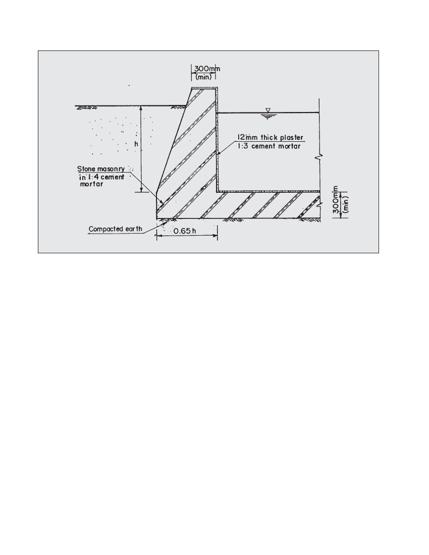
Figure 5.9 Wills and floors of water retaining
If the vertical face is towards the soil, the water volume in
the basin will increase but structural stability will be
slightly reduced.
The internal surface (water retaining surface) of the walls
and the surface of the floor should be plastered using 1:3
cement sand mortar to a thickness of 12 mm. This
significantly minimises the likelihood of seepage.
Finally, the walls and the floor should be cured as discussed
in Chapter 4. Another option is to use reinforced concrete
for the floor and walls. However this is more expensive
and also requires skilled labour, so is not generally
recommended for micro-hydro schemes.
5.6 Checklist for gravel trap,
settling basin and forebay work
Can the gravel trap, settling basin and the forebay or at
least two of these structures be combined together?
Are these structures located such that excess water can be
spilled safely, without causing erosion or stability problems?
Is the settling basin sized such that the emptying frequency is
once to twice daily during high flows? Also, does dlimitcorrespond
to the head and turbine type? Refer to Section 5.3.3.
Is secondary settling required at the forebay? Is the forebay
large enough for manual cleaning and is a spillway
incorporated in this structure? Has the submergence head
been checked?
Once these structures have been sized, refer to Section 5.5
for the construction details