110 CIVIL WORKS GUIDELINES FOR MICRO-HYDROPOWER IN NEPAL
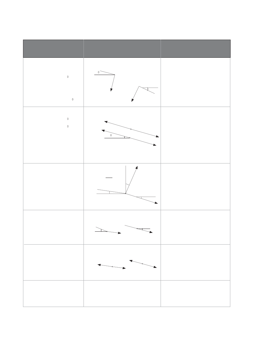
TABLE 7.2 Forces on anchor and slide blocks
FORCES (kN)
F1
F1 = combination of Flu and Fld
F = (W +W )L
lu p w lu
cos ∞
Fld = (Wp +Ww )Lld cos β
If pipe is straight,
F = (W + W )(L +L )cos∞
1 p w lu ld
DIRECTION OF POTENTIAL MOVE-
MENT OF ANCHOR BLOCK OR
SUPPORT PIER
Uphill portion Downhill portion
∞(
F1u
F1d β
SYMBOLS ARE DEFINED AT THE
END OF THIS TABLE
F1 is the component of weight of
pipe and water perpendicular to the
pipe.
Applies to both support piers and
anchor blocks
F2
F
2u
=
f(W +W
pw
)L Cos
2u
∞
F2d = f(Wp+Ww )L2dCos ∞
F3
F3 = 2ywater htotalx( Πd2 /4)
sin(β - α)/2
= 15.4htotal d2 sin(β - α)/2
Expansion: anchor
below and expansion
joint above
F2
∞
Contraction: anchor below
and expansion joint above
F2
Directions for forces on support pier
F2 is the frictional force due to the
pipe sliding on the support piers.
Applies to support piers and
anchor blocks. The force acting at
an anchor block is the sum of
forces acting on the support blocks
between the anchor block and
expansion joints, but opposite in
direction.
α+β
2
α
F3
β
F3 is the hydrostatic force on bends
that acts along the bisector of the
bend.
Only applies to anchor blocks that
have horizontal and/or vertical bends
F4
F = combination of F and F
4 4u 4d
F4 = Wp L4u sinα
F4d = Wp L4d sinβ
F5
F5 = 1000Ea TΠ (d+t)t
SeeTable 6.2 in Chapter 6 for
values of E and a
F
6
F = 100d
6
Uphill portion Downhill portion
α
F4u
β
F4d
Uphill portion
Downhill portion
F5d
F5u
F direction as F
65
F4 is the component of pipe weight
acting parallel to pipe.
Applies to anchor blocks only.
Calculate only if the angles (α or β)
are larger than 20°.
F5 is the thermally induced force
restrained by the anchor block in the
absence of an expansion joint.
Applies to anchor blocks only.
Calculate only if expansion joints are
not installed between anchor blocks.
F is the factional force in the
6
expansion joint. The F6 force is felt
because the joint will resist sliding.
Applies to anchor blocks only.