Tri-BotHack
Problem/Finish Description
- Get all 5 tribots running
- Begin programming tribots to go in a patterns like squares, circles
- Add remote emergency take over capability
- Add automous ability to travel the cooridors of first floor Clark Library Building
- Add features from the head
- Replace arduino with papilio
- Pull all existing documentation into one place in the below context
Conceive
Project was inspired by this video that shows a robot balanced on top of a basketball. A completely powered Omni wheel connected to some accelerometer/gryo can create a powered unicycle that moves sideways. This is completely different than the one wheel motor cycle, the monocycle or the R.O.I.T wheel.
The goal is to duplicate the robot balanced on top of a basketball and ultimately duplicate the powered unicycle.
Hack a Toy

Tribot
The WowWee Tribot seemed a very close match to the robot balanced on a basketball.
-

WowWee Tribot
-
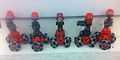
6 Tribots have been purchased, one is dedicated to spare parts
WowWee Tribots retail anywhere from $300 and below here The robot is officially called the "WowWee Tribot Talking Companion." There is a Wowwee Mini Tri-bot that retails for around $21 that should not be confused with the bigger brother. Online it is hard to tell them apart. The Mini Tri-bot does not ship with universal or Omni wheels.
Design
Reverse engineering a toy is similar to forward design. It starts with re-creating the implmentation/operation documentation that already exists.
Wheel Design Review
-
Riot Wheel Toy video
-
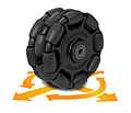
Omni Wheel
-
Mecanum Wheel
-
Fordson screw wheel original video video failure
Major Hardware Systems to be connected to Arduino
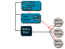
These are the major hardware systems within the Tribot that needed to be connected to the Arduino:
- batteries
- motors
- head
- encoders (counts motor/wheel revolutions and direction of rotation)
- IR reflection sensors
- Remote Controller (including tilt sensor in remote)
- speaker
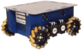
The current base is too low to the ground to work on top of a basketball. So the base needs to be redesigned.
New Base Design
Drew using 3DTin following these tutorials.
-
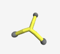
3D drawing of side view of original tribot base
-
3D drawing of base of tribot from below
-
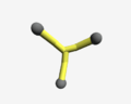
this is the second base idea. The wheel stems are at an angle instead of parallel to the ground
-
side view of second base idea. wheel stems are angled instead of parallel
-
Above view of the third base idea
-

Side view of third idea. "Conical shape" base. The cone would allow it to sit atop the basketball a little easier. The wheel stems would also be at an angle and not parallel
-
side view of the fourth base option. requires an extension from the base setup that is already there
-
view from above of the 4th base idea
-
view from under of 4th base idea
-
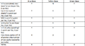
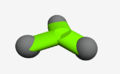
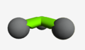
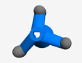
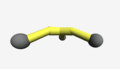
Decision matrix for new tribot base
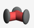
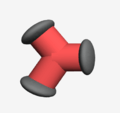
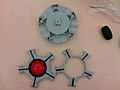
Red base The red base is the original tribot base. The wheel "stems" are parallel to the ground. This current base does not allow the Tribot to sit and roll atop of a basketball.
Green base The green base is a new idea for Tribot. The wheel stems would be tilted at an angle so that it would be easier to fit on a ball. This requires almost creating a new base.
Blue base The blue base is another idea. Its a conical base. A hollow cone would allow it to perfectly sit on a basketball I think. Additionally, the wheel stems would have to be recreated similar to the idea in the green base. They would also have to be slanted at an angle.
Yellow base The yellow base is the last idea I had. The yellow base is using the original base but adding extensions to the ends. It would be adding the extensions at an angle.
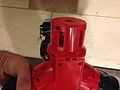
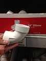
NEW BASE Started by testing with one 45° elbow shaped 1 1/2" pvc pipe. The motor fit inside perfectly. But wheel could not attach to the motor normally. Had to do some sanding. Video of the result. May have to dedicate a robot to the ball. Seems weaker trying to run motor test with the new base video.
-
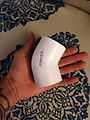
Used a 1 1/2" 45° elbow pvc pipe to add to the current tribot's base
-
2 out of 3 openings/slots on where the motor holds itself in place on the current tribot's base
-
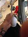
Cutting the marked openings with a hacksaw in order for the motor to fit in place
-
Comparison Pvc vs Current base
-
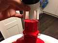
Put the motor into the put pvc pipe and it fitted almost perfectly
-
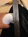
Sanding the edges down so that the wheel spins properly with out any obstruction.
-
Opened up the base and took all three motor out so that the cables would be long enough with the new addition
-
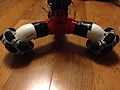
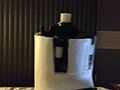
Because the pipes are at a 45° angle, the wheels are also at an angle and not parallel to the ground.
-
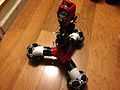
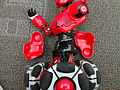
Tribot with all three pvc pipes temporarlly attached with gorilla tape
Next Step May be able to use PVC pipe to pivot wheels for both ground and ball use.
-
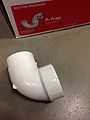
90° elbow pvc
-
P Trap pvc
-
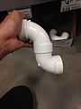
Perfect new base so that the all wheels become parallel to the ground.
Implement
These are the steps to take apart a toy Tribot WowWee and add an arduino
Do not remove the wheels
-
motor's go bad and need to be replaced .. remove wheel only for this reason
-
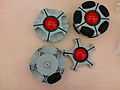
assembled and disassembled wheels
-
parts of one wheel
Taking apart the Body
-
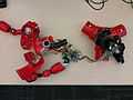
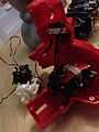
Tri-Bot disassembled, arms have no motors in them ... remove them
-
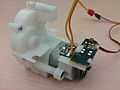
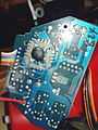
Tri-bot circuit boards (digital and motor control close up
-
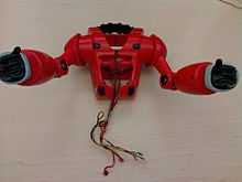
Arms Removed 3 pairs of IR transmitter and receiver cables visible
-
Speaker in the Breast Plate
-
Remove hip pieces
Remove the Arms
The arms are held on by three screws around the arm socket and one screw at the waist. Remove them. The black handle is held on with two screws. Do not remove them. The goal is to keep the arm assembly together as much as possible. There are two screws near the black handle, towards the back near the back IR transmitter and receiver. Remove one of these screws. The split apart the arms. The black handle should hold the shoulders together. There is a white bar that holds the back shoulders together. Replace the last screw removed.
The breast plate is a speaker. There are 3 infared transmitters and 3 receivers. They are used for the "Home" function where the robot follows someone with the remote and are used to avoid collisions. This tutorial does not show how to restore this functionality with the arduino.
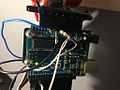
Remove Existing Logic Board
Remove Existing Logic Board
-
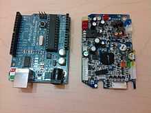
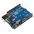
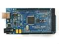
Arduino vs Existing Logic Board
Four screws hold on the existing logic board. The Arduino almost fits 2 of the screws. One screw has to be forced in at an angle, the Arduino UNO mounts at two points. The arduino is larger than the original logic board therefore putting the arms back on over the new arduino like they went over the old logic board is not an option.
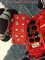
Hack the Existing Motor Controler
-
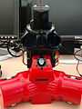
Expose the Motor Controler ... it is wedged in .. carefully watch how it comes out ... visualize putting it back in ... Is tricky
-
... Cut off the ribbon cable that was connected to the old logic board
-
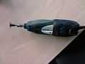
get a dremel or drill
-
put a rotating cutting wheel on the end of it
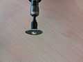
-
cut out the digital part of the motor controller, be careful to leave the soldering pads to use in the next step ... want to remove the circuit board (and chip under the black blog) from the circuit and replace with arduino
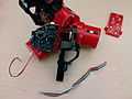
-
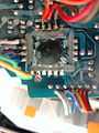
solder the ribbon cable as in this photo .. notice the cut off corner of the circuit board that we are removing from the circuit
Connecting cables to Arduino
Cable Harness A color code has been developed that maps colors to Arduino pin numbers:
| Motor | Function | Color | Arduino Pin |
|---|---|---|---|
| 1 | yellow | on/off | 12 |
| 2 | teal | on/off | 11 |
| 3 | blue | on/off | 10 |
| 1 | white | direction | 9 |
| 2 | gray | direction | 8 |
| 3 | purple | direction | 7 |
| 1 | orange | encoder | 6 |
| 2 | red | encoder | 5 |
| 3 | brown | encoder | 4 |
| head switch | white | start | 3 |
-
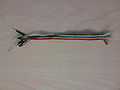
Ribbon cable built after soldering to motor controller with shrink-wrapped leads on one end, ready to plug into the Arduino
-
closeup of ribbon cable
The power cables are blue and black .. and sometimes a bit thicker:
-
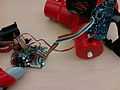
Spliced blue & black cables coming from the battery power line & Pull down resistor for head switch ... stranded cables need to be replaced with solid wires
-
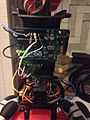
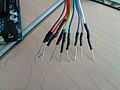
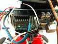
All cables plugged into the Arduino pins, stranded cables need to be replaced with solid wires
-
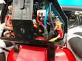
power line spliced blue wire connected to the red, black wire spliced into the original black wire, everything shrink wrapped
The head switch needs to be re-attached to the arduino:
-
Tribot head switch with white wires coming out of it going to Arduino
-
Can see power (blue) going into arduino, then black (ground) to batteries, then white through resistor to pull voltage down to zero when head switch is open and finally white supplying power to the head switch
-
When the head is down, 5 volts bounces off the top of the resistor to the Arduino digital pin, when head is up, the Arduino digital pin is pulled to ground through the resistor.
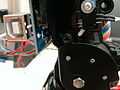
Connecting Encoder
Not much work has been done.
-
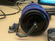
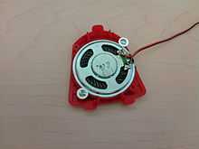
can see three wires:brown,red and orange leaving encoder
-
Encoder is electronics that is counting shadows of the fan wheel passing through it
-
The orange wire from the three motors could go to pins 2,1 and 0 but these leaves only ping 13 free
This much about the wiring is known:
- brown - ground
- red - 5 volts
- orange - pulses about 0.25 ms long .. was measured with the Digilent Electronics Explorer
The arduino encoder web site talks about how it is hard to count these pulses ... all the code is playing with the interrupts of the arduino amtel processor. This means that the code can do nothing else .. and we want the code to turn the motors, look at IR sensors, etc. Probably going to have to build a special circuit to do this out of an FPGA papilio.
Connecting the Head
-

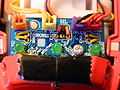
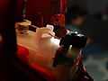
Tribot head showing eyebrows going up, ears popping out, bright LED lifting out top of head and teeth light up ... Video
-
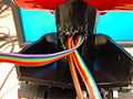
cables coming out of the head ... lots of them .. have accidentally the head to change ... need to figure out what the wires do ... start by taking apart a head ... taking pictures ... activating the moving pieces ... turning on/off LEDs and then putting back together
-
The small arduino's used now are not going to work ... need an arduino mega so there are enough pins
-
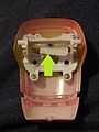
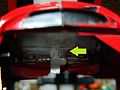
Structure of the face. Push up where the green arrow is and the eyebrows move up and down.
-
Panel inside the face. Inside the head on the very front, there's a panel where all the wires in the head are attached to.
-
LED light inside the tribot. Where green arrow is where you can see the orange and black wires
-
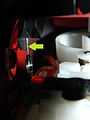
that spring is what pulls the LED light up and down
-
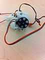
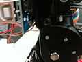
motor inside the head
CircuitBoard in Head Wires:
- purple is 4V
- blue is connected to the left eye
- green is connected to the right eye
- yellow is connected to the right ear
- orange is connected to the left ear
- red is connected to mouth "m"
- brown is connected to the mouth "r" (right??)
There are 3 wires under a label "HL". HL is headlight. The purple box is where power is connected to.
Video of trying to connect power to the head. It is not straight forward. Need to apply power slowly.
Gyro-Accelerometer
-
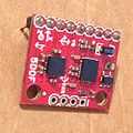
5DOF Five Degrees of Freedom Part# SEN-09268
-
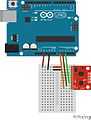
Accelerometer and Arduino were connected as indicated
The 5DOF The 5DOF is called an "Inertia Measurement Unit" that measures the following:
- Roll
- Pitch
- Position along X-axis
- Position along Y-axis
- Position along Z-axis
It has been retired by sparkfun meaning that it can no longer be purchased. But it exists in Fritzing so it is easy to draw a circuit with it.
Connecting to the Arduino Leveraged this example. A breadboard was necessary because the pins don't match the arduino headers. The alternative was to solder. Ths is how it was connected. At first only the accelerometer was connected, then the gyro was added.
| IMU Pins | Arduino Pins |
|---|---|
| 3.3V | 3.3V |
| Ground | Ground |
| X-Acc | A0 |
| Y-Acc | A1 |
| Z-Acc | A2 |
| X-Rate (formerly Vref) | A3 |
| Y-Rate | A4 |
| EMPTY (formerly x-rate) | A5 |
The starting point sketch worked except for the "zero-reading." Hypothesis is it varies from unit to unit. The code was modified to take into account the "zero-reading" in the serial output display.
Results Can see readings changing as it is moved around by hand.
-
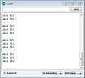
Accelerometer's raw zero reading with no adjustments in code
-
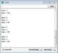
Accelerometer's reading after adjusting for "Zero-reading" i.e. parallel with the ground
-
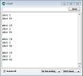
Accelerometer's reading "Counter-Zero" reading i.e. inverted and parallel to the ground
-
Accelerometer's Vertical reading i.e. perpendicular to the ground
-
Accelerometer's "Counter-Vertical" reading i.e. inverted and perpendicular to the ground
Operate
- Find screwdriver that works
- Put batteries in (8 AA batteries)
- Turn on
- Push head down
- Turn off
- Take batteries out
Creating Program to go in a Square
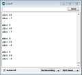
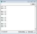
Use the Motor test to see a "skeleton" of what the coding in Tribot should look like. The setup() tells you which pins are wired to what. The loop() tells you all of the commands Tribot will follow. In this case it's
-one motor at a time
-spin tight CCW
-one motor at a time
-spin tight CCW
-spin tight CW
-gradual turn
-forward
-backward
-right forward
-right backward
Each command is followed by a delay of 1000 miliseconds
Decide what new pattern will be
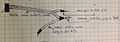
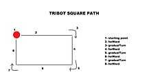 the path that Tribot follows to go in a square using the different commands |
Envision what you want the Tribot to do. In this case, it needs to go in a square. A square looks like the graphic above. This new pattern begins with a starting point, then a forWard command from the point then a gradualTurn then forWard then gradualTurn then forWard then gradualTurn and lastly one more forWard command.
Change the original
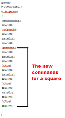 The new commands inserted into the loop() section of the Arduino code. The new commands allow Tribot to go in a square pattern. |
Copy the original code into a word document. Decide what you want in the new code. In the loop() part of the code, erase what you do not want. At the end, insert the new commands that will make a square. The new commands come from the graphic of the path. Each command is followed by a 1000 millisecond delay. After the loop comes the individual sections for each command. They're titled "void (insert name)". Keep only the commands that you will be using. Erase the rest of the sections.
The final code The final code should look like this:
Troubleshooting
Powering Tribot If batteries are left in the tribot, they will corrode the battery case. The problem can be solved by scrapping off the corrosion. Corrosion is mostly found on the removable red lid, but it also occurs at the top of the battery, deep inside the base.
-
No corrosion found on battery pack
There is a black button in the base of the Tribot that has to be pressed to turn it on.
If the batteries are good, an LED on the arduino will glow.
If the head switch is jammed or not connected, then pressing the head will not start the program.
-
tribot head switch, not activated
-
tribot head switch, activated
Wheels spin when turning on Send motor test to the arduino. It probably has another program loaded.
Demo
Seminar Presentation 2014MAR20
A demonstration of a working tribot with the Motor test installed is shown on the following video: Tribot Demo Test
Next Steps
- Explore possibilities of line-following tribot
- Apply power to the head and try to control it's features with arduion
- Start capturing wheel turning information from the encoder
- Test new base to see if tribot can work equally well on ground and ball
- Define working, test all 5 and document current status
- Add simple mechanism so that all 5 spill out of a door when is opened
- Add remote controller
- Add speakers
- Determine if accelerometer and gyro have to be calibrated, start testing with PID software