Structures
Part of the Statics course offered by the Division of Applied Mechanics, School of Engineering and the Engineering and Technology Portal
Lecture
Structural engineering relies heavily on the strengths of materials and their ability to withstand forces of tension, compression & shear. When used in conjunction with each other, as in the case of a truss, individual load bearing members both share and transmit loads, enabling the structure to accomplish much more than any individual member could alone.
Plane Trusses
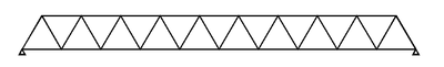
One way of distributing the force across a large distance is by building a Plane Truss, which takes advantage of the principle of Equilibrium to translate forces along a system of interconnecting members.
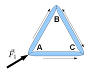
A simplest truss is a triangle made of three points: A, B and C, and three members: AB, BC and CA. The method of distributing forces amongst many members relies on the engineer's ability to place a tensile or compressive force at any particular location. To properly sum forces at a particular point, one must be able to sum forces into that point and also away from it. Thus, AB and AC are in compression while BC is in tension.
Method of Joints
The principle of equilibrium may be used to solve the loads impinging upon a massless truss by analyzing the effect of each load at a single point on the truss. Each load is broken down into its  and
and  component vectors and these are summed to equal zero at a particular point on the truss (e.g. A). Similarly, each load creates a moment rotating about that same point A and these may also be summed together to equal zero. Therefore, given enough information about the loads applied, any of the other loads may be calculated.
Therefore, the Method of Joints may also be applied to a truss joint to determine the force (compressive or tensile) in each member of the truss. A place where the forces and members meet may become the joint to be examined (A), and the principle of equilibrium is applied, thus solving the question of where the forces are transmitted in that truss around that joint.
Example:
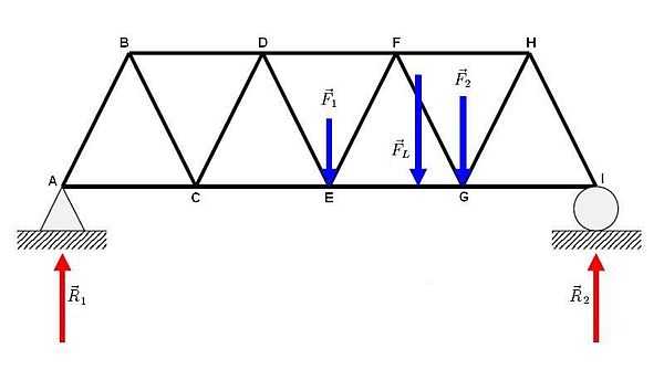
Consider a truss bridge under loads  ,
,  and
and  . What are the forces in each of the members of the loaded truss, under the loads applied?
Assume that  ,
,  and
and  . Also assume that each member AB, CE etc. has a length of
  meters long and that is
  from
from  .
.
Solution:
First we must solve the external forces on the truss completely. We do so by analyzing the free body diagram. Equilibrium dictates that  and
and  .
.
First we sum the moments about a particular point. In this case, let's use A:

Or...

.
We may sum the forces around an arbitrary point A. There are no components of the force vectors, so  .
.
 .
.
Or...
 and...


Secondly, we may begin to solve for the internal forces within each member by summing the forces around point A at the location of  .
.

Or...
(in Compression)

Or...
(in Tension)
Each successive member may be analyzed for its internal forces, be they compressive or tensile in a similar manner. For a successful analysis of every member of the truss, it is imperative that every external force be included. Therefore it is advised that the engineer begin analysis by the method of joints at each joint where external forces have been resolved and work his or her way inward towards the center.
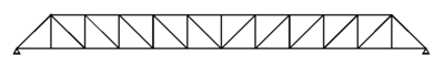
Method of Sections
If every joint in a structure does not need to be analyzed, yet the internal forces of some members need to be resolved, a potential shortcut method is the method of sections. The method of sections involves cutting a truss into a smaller part, thus changing the internal forces in the members in question to external forces, which may easily be solved by the method of Equilibrium.
Example:
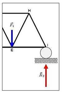
If the truss shown here were to need analysis for the internal forces on one particular member, EF, the method of sections could be used. Here we use the previous values for and  . Also assume that each member is
  meters long.
Solution:
We solve the external forces on the truss completely. Equilibrium dictates that and .
Once again, we first sum the moments about a particular point. In this case, let's use I:

Or...

(in tension).
Space Trusses
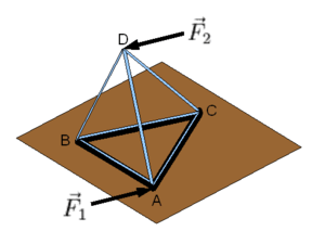
A Space Truss is a 3D plane truss. Made up of similar structural forms, the space truss is a much more realistic form of truss than the Plane Truss. Calculation and resolution of loads, external and internal forces is performed the same way, however, care must be made to ensure that all three dimensions are correctly examined and properly resolved. Once again and .
Assignments
Activities:
- Create an activity
Readings:
- Peruse the appropriate sections of b:Statics
- Solved Problem on method of joints for calculating member forces in plane truss
- Introduction to Structural Design, Virginia Tech.
Study guide:
- Wikipedia article:Plane Truss
- Wikipedia article:Tension
- Wikipedia article:Compression
- Wikipedia article:Method of Joints
- Wikipedia article:Method of Sections
- Wikipedia article:Space Truss
Resources