Radiation astronomy/Satellites
< Radiation astronomy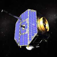
Radiation satellites may be designed and built for detection in one particular radiation astronomy or for many. Some have been built for more than one purpose or for a different purpose entirely.
To place sensors (or detectors) above the Earth’s atmosphere is often a necessity for radiation astronomy. “The sensors at once lose the basic advantage of both radio and optical telescopes, a rigid, well-surveyed foundation upon a well-behaved earth.”[1] “The source locations, therefore, reflect uncertainties in both the sensor data and in vehicle aspect.”[1]
Astronomy
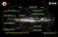
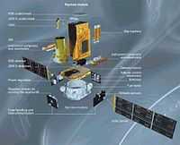
"Gaia [NSSDC/COSPAR ID: 2013-074A] is a European Space Agency astronomy mission whose primary goals are to: (1) measure the positions and velocity of approximately one billion stars; (2) determine the brightness, temperature, composition, and motion through space of those stars; and, (3) create a three-dimensional map of the Milky Way galaxy."[2]
At left is an image of the Milky Way galaxy depicted onto it the various targets and experimental regions for the ESA Gaia spacecraft.
"Repeatedly scanning the sky, Gaia will observe each of the billion stars an average of 70 times each over the five years. It will measure the position and key physical properties of each star, including its brightness, temperature and chemical composition."[3]
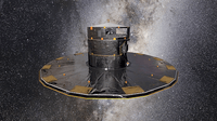
At lower right is an image from an animation that has the Gaia spacecraft spinning slowly (four revolutions per day) to sweep its two telescopes across the entire celestial sphere.
Radiation
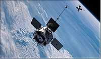
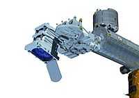
"The Radiation Belt Storm Probes [RBSP, NSSDC/COSPAR ID: 2012-046A, now the Van Allen Probes] mission is part of NASA's Living With a Star Geospace program to explore fundamental processes that operate throughout the solar system, in particular those that generate hazardous space weather effects near the Earth and phenomena that could affect solar system exploration. RBSP is designed to help understand the sun's influence on the Earth and near-Earth space by studying the planet's radiation belts on various scales of space and time. Understanding the radiation belt environment and its variability has extremely important practical applications in the areas of spacecraft operations, spacecraft and spacecraft system design, mission planning, and astronaut safety."[4]
"The mission's science objectives are to: (1) discover which processes, singly or in combination, accelerate and transport radiation belt electrons and ions and under what conditions; (2) understand and quantify the loss of radiation belt electrons and determine the balance between competing acceleration and loss processes; and, (3) understand how the radiation belts change in the context of geomagnetic storms."[4]
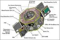
"The Energetic Particle, Composition and Thermal Plasma Suite (ECT) ... directly [measures] near-Earth space radiation particles to understand the physical processes that control the acceleration, global distribution, and variability of radiation belt electrons and ions. The objectives of the experiment are to: (1) determine the physical processes that produce radiation belt enhancements; (2) ascertain the dominant mechanisms for relativistic electron loss; (3) determine how the intter magnetospheric plasma environment controls radiation belt acceleration and loss; and, (4) develop empirical and physical models for understanding and predicting radiation belt space weather effects. In order to accomplishments these goals, ECT consists of three instruments: the Magnetic Electron Ion Spectrometer (MagEIS), the Helium Oxygen Proton Electron electrostatic analyzer (HOPE), and the Relativistic Electron Proton Telescope (REPT)."[4]
"The Radiation Belt Storm Probes Ion Composition Experiment (RBSPICE) is intended to determine how space weather creates the so-called "storm-time ring current" around the Earth and ascertain how that ring current supplies and supports the creation of radiation populations. The investigation [measures] the ring current pressure distribution, needed to understand how the inner magnetosphere changes during geomagnetic storms and how that environment supplies and support the acceration and loss processes involved in creating and sustaining hazardous radiation particle populations. The experiments objectives are to: (1) understand the effects of the ring current and other storm phenomena on radiation electrons and ions; (2) examine how and why the ring current and associated phenomena vary during storms; and, (3) support the development and validation of specification models of the radiation belts for solar cycle time scales."[5]
"The Relativistic Proton Spectrometer (RPS) [measures] inner radiation belt protons with energies from 50 MeV-2 GeV. Such protons are known to pose a number of hazards to humans and spacecraft, including total ionizing dose, displacement damage, single event effects, and nuclear activation. The objectives of the investigation are to: (1) support the development of a new AP9/AE9 standard radiation model for spacecraft design; (2) to develop and test the model for RBSP data in general and RPS specifically; and, (3) to provide standardized worst-case specifications for dose rate, internal and deep dielectric chargins, and surface charging."[6]
At left is a diagram of one of the Van Allen Probes labeling various subsystems including the ECT.
Planetary science
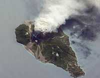
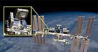
Oblique images such as the one at right are taken by astronauts looking out from the International Space Station (ISS) at an angle, rather than looking straight downward toward the Earth (a perspective called a nadir view), as is common with most remotely sensed data from satellites. An oblique view gives the scene a more three-dimension quality, and provides a look at the vertical structure of the volcanic plume.
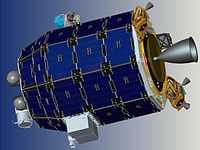
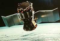
"The Lunar Atmosphere and Dust Environment Explorer (LADEE, at left) launched 07 September 2013 at 03:27 UT (06 September 11:27 EDT) on a Minotaur-V from Wallops Flight Facility. LADEE is designed to characterize the tenuous lunar atmosphere and dust environment from orbit. The scientific objectives of the mission are:(1) determine the global density, composition, and time variability of the fragile lunar atmosphere; and, (2) determine the size, charge, and spatial distribution of electrostatically transported dust grains and assess their likely effects on lunar exploration and lunar-based astronomy. Further objectives are to determine if the Apollo astronaut sightings of diffuse emission at 10s of km above the surface were Na glow or dust and document the dust impactor environment (size-frequency) to help guide design engineering for outpost and future robotic missions."[7]
"The orbiter will carry a Neutral Mass Spectrometer (NMS), an Ultraviolet/Visible Spectrometer (UVS), and a Lunar Dust Experiment (LDEX)."[7]
"The NMS is a quadrupole mass spectrometer designed ot detect species up to 150 amu and will look for CH4, S, O, Si, Kr, Xe, Fe, Al, Ti, Mg, OH, and H2O. The UVS will detect Al, Ca, Fe, K, Li, Na, Si, T, Ba, Mg, H2O, and O and will monitor the dust composition. The LDEX is an impact ionization dust detector designed to measure particles down to 0.3 microns at the spacecraft altitude. The LLCD is a test of a high data-rate optical (laser) communications system."[7]
Colors
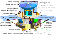
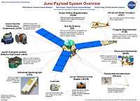
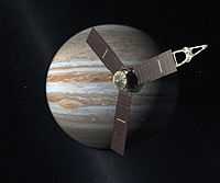
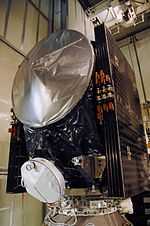
"Juno [NSSDC/COSPAR ID: 2011-040A] is also carrying a colour camera, promising Earthlings "the first detailed glimpse of Jupiter's poles"."[8]
"The Juno mission was launched on 05 August 2011 to study Jupiter from polar orbit for approximately one year beginning in 2016. The primary scientific objectives of the mission are to collect data to investigate: (1) the formation and origin of Jupiter's atmosphere and the potential migration of planets through the measurement of Jupiter's global abundance of oxygen (water) and nitrogen (ammonia); (2) variations in Jupiter's deep atmosphere related to meteorology, composition, temperature profiles, cloud opacity, and atmospheric dynamics; (3) the fine structure of Jupiter's magnetic field, providing information on its internal structure and the nature of the dynamo; (4) the gravity field and distribution of mass inside the planet; and (5) Jupiter's three-dimensional polar magnetosphere and aurorae. Juno carries eight experiments to achieve these objectives."[9]
"The spacecraft is built around a hexagonal cylinder bus measuring 3.5 m in diameter by 3.5 m high. Three solar panel wings extend from alternate sides of the hexagon giving a total diameter of approximately 20 m. A high gain antenna is mounted on top of the bus, with instruments mounted on the deck and propellant, oxygen, and pressurant tanks mounted within. At the center of the top deck is a 0.8 x 0.8 x 0.6 m titanium "vault" which houses the spacecraft avionics and critical systems to protect them from the severe jovian radiation environment. The vault has a mass of 150 kg and walls up to over a cm in thickness. Power is provided by ultra triple junction GaAs solar cells, covered with thick glass for radiation shielding, which are grouped into 11 solar panels, four on two of the wings and three on the other. (The end of the third wing is a boom structure holding science instruments.) The solar panels will produce a total of 18 kW at Earth and 400 W initially at Jupiter. The science payload comprises ten instruments: the Jovian Auroral Distributions Experiment (JADE), the Jupiter Energetic-particle Detector Instrument (JEDI), the Ultraviolet Spectrograph (UVS), the JunoCam, the Jovian Infrared Auroral Mapper (JIRAM), the Plasma Waves Instrument (Waves), the Microwave radiometer (MWR), the Fluxgate Magnetometer (FGM), the Advanced Stellar Compass (ASC), the Scalar Helium Magnetometer (SHM), and the Gravity Science experiment."[9]
Minerals
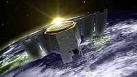
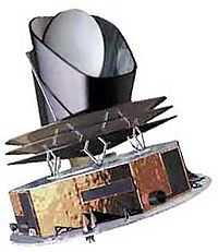
"The scientific purpose of the Aeronomy of Ice in the Mesosphere (AIM, [NSSDC/COSPAR ID: 2007-015A]) mission is focused on the study of Polar Mesospheric Clouds (PMCs) that form about 50 miles [60 km] above the Earth's surface in summer and mostly in the polar regions. The overall goal is to resolve why PMCs form and why they vary."[10]
"AIM will measure PMCs and the thermal, chemical and dynamical environment in which they form. This will allow the connection to be made between these clouds and the meteorology of the polar mesosphere. This connection is important because a significant variability in the yearly number of noctilucent ("glow in the dark") clouds (NLCs), one manifestation of PMCs, has been suggested as an indicator of global change."[10]
"The AIM scientific objectives will be achieved by measuring near simultaneous PMC abundances, PMC spatial distributions, cloud particle size distributions, gravity wave activity, cosmic dust influx to the atmosphere needed to study the role of these particles as nucleation sites and precise, vertical profile measurements of temperature, H2O, OH, CH4, O3, CO2, NO, and aerosols. AIM carries three instruments: an infrared solar occultation differential absorption radiometer, ... (Solar Occultation for Ice Experiment, SOFIE); a panoramic ultraviolet imager (Cloud Imaging and particle Size Experiment, CIPS); and, an in-situ dust detector (Cosmic Dust Experiment, CDE)".[10]
"The solar occultation for ice experiment (SOFIE) is an infrared radiometer experiment that uses a differential absorption technique in solar occultation (sunrise and sunset). SOFIE measures absorption of sunlight in eight spectral regions between 0.25 and 5.3 mm. The specific wavelengths are chosen to provide altitude profiles of temperature, polar mesospheric clouds (PMCs), water vapor, Carbon Dioxide, Methane, Nitric Oxide, Ozone and aerosol absorption."[11]
"The cloud imaging and particle size experiment (CIPS) is a UV panoramic imager that uses intensified CCD cameras to image the Polar Mesospheric Clouds (PMC) latitude versus longitude distribution. It provides nadir imaging with a 120 degrees by 80 degrees field of view (1140 by 960 km) with at least 3 km spatial resolution at 83 km. CIPS observes the backscattered radiance from PMCs (near 82 km altitude) to derive the morphology of PMCs and the cloud particle sizes. Rayleigh scattering from the background near 50 km altitude is used to measure gravity wave activity. Multiple exposures of individual cloud elements provide a measurement of the scattering phase function and detect spatial scales ~2 km. The Ultraviolet bandpass (265 plus or minus 5 nm) maximizes cloud contrast."[12]
"The cosmic dust experiment (CDE) is an in-situ dust detector that measures the influx of dust particles into the upper atmosphere (the PMC region). The CDE is mounted on the zenith side of the spacecraft, with a very wide field of view looking away from the Earth."[13]
Theoretical radiation satellites
Def. “[a] man-made apparatus designed to be placed in orbit around a celestial body, generally to relay information, data etc. to Earth”[14] is called a satellite.
Ideally, a radiation satellite has a detector or sensor system aboard for each of the many types of radiation the probe is likely to encounter. These systems are balanced against support requirements to optimize the probes performance.
Satellites often spin at a fairly constant rate to allow each detector access to the targets. Spinning may give the detector system stability.
Supplying power, usually in the form of electricity, often comes from photocells. Interplanetary and interstellar craft need other sources such as radionuclides in high concentration.
Entities
"Space is considered an environment — an extreme environment, filled with entities that can be harmful to spacecraft."[15]
"In space, there are several environmental threats that can harm materials used to create spacecraft. These threats include ultraviolet rays and x-rays from the sun; solar wind particle radiation; thermal cycling (hot and cold cycles); space particles (micrometeoroids and debris); and atomic oxygen."[15]
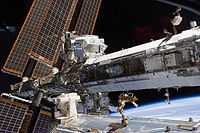
"Since 2001, NASA and its partners have operated a series of flight experiments called Materials International Space Station Experiment, or MISSE. The objective of MISSE is to test the stability and durability of materials and devices in the space environment."[15]
"PECs [Passive Experiment Containers], which are attached to the exterior of the International Space Station, are about 2-feet by 2-feet and hold a variety of materials samples and devices whose reactions in space are of interest."[15]
"The PECs are positioned in either a ram/wake orientation or in a zenith/nadir orientation. The ram orientation is the direction in which the space station is traveling, and the wake orientation faces the direction traveled. The zenith orientation faces away from Earth into space, while the nadir orientation faces straight down to Earth. Each orientation exposes the samples to different space environmental factors."[15]
Sources
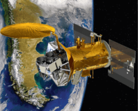
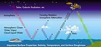
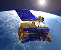
"Many natural sources, besides salinity, contribute to the microwave radiation at L-band frequencies (approximately 1 gigahertz) measured by satellites. Correcting the influence of these natural sources is a key to obtaining Aquarius’ accurate salinity measurements."[16]
"Aquarius is dedicated to making precise measurements of ocean salinity over months and years, providing important new information for climate studies. It will produce monthly maps of the surface salinity of the global ocean with a 93-mile (150-kilometer) resolution and an accuracy of 0.2 practical salinity units, which is equal to about one-eighth teaspoon of salt in a gallon of water. (Practical salinity is a scale used to describe the concentration of dissolved salts in seawater, nearly equivalent to parts per thousand.) The mission is to make these measurements continuously for at least three years."[16]
"The radiometers on Aquarius measure the microwave emissions from the sea surface at 1.4 gigahertz in the L-band portion of the electromagnetic spectrum. This energy, which is measured as an equivalent temperature called the "brightness temperature" in Kelvin, has a direct correlation to surface salinity."[16]
Meteors
"At the Kennedy Space Center [...], engineers are assessing options for fixing a radiator panel mounted on the inside of the shuttle Atlantis' right-side payload bay door. The panel apparently was damaged when a piece of space debris or a micrometeoroid slammed into the radiator, presumably during the shuttle's flight last month [September 2006], blasting .108-inch-wide hole in the upper surface and destroying the aluminum honeycomb material below before exiting the other side."[17]
"The impact did not threaten the crew and the damage can be repaired. But it illustrates the danger posed by micrometeoroid/orbital debris (MMOD) and the reason why NASA considers such strikes a high risk. The odds of a catastrophic impact-related entry failure range between 1-in-210 to 1-in-350, depending on whether the astronauts inspect the ship in orbit prior to re-entry."[17]
"A preliminary engineering analysis shows the impact in question was one of the most significant instances of MMOD damage in shuttle history, second only to a cargo bay door impact during shuttle mission STS-72 in 1996."[17]
"The shuttle's 60-foot-long payload bay doors each feature four radiator panels that are exposed to space once the doors are opened in orbit. The forward two radiator panels measure about one inch thick, feature Freon coolant tubes positioned about 1.9 inches apart and can pivot to radiate from both sides. The aft panels are fixed and only radiate from one side. They measure a half inch thick and feature coolant tubes separated by about 5 inches. The interior of the panels is made up of an aluminum honeycomb material."[17]
"The impact on Atlantis's right-side, or starboard, radiator was found roughly midway between two coolant lines on panel No. 4. The object blasted a .108-inch-wide hole and presumably broke apart on impact. The resulting spray of debris created a cone-shaped damage cavity immediately below the face plate, destroying the honeycomb interior to the full half-inch depth of the panel. The lower face sheet was pushed out in two places. A .26-inch crack and a .03-inch-wide exit hole were found."[17]
"At orbital velocities, even tiny pieces of debris pose a serious threat. An aluminum sphere just .4 inches across moving at 10 kilometers per second, or 22,370 mph, carries the same impact energy as a bowling ball moving at 300 mph."[17]
Cosmic rays
The Alpha Magnetic Spectrometer "is designed to search for various types of unusual matter by measuring cosmic rays."[18]
"About 1,000 cosmic rays are recorded by the instrument per second, generating about one GB/sec of data. This data is filtered and compressed to about 300 KB/sec for download to the operation centre POCC at CERN. In July 2012, it was reported that AMS-02 had observed over 18 billion cosmic rays.[19]"[18]
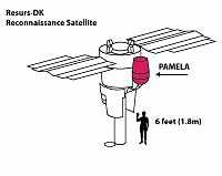
The Payload for Antimatter Matter Exploration and Light-nuclei Astrophysics (PAMELA) "is an operational cosmic ray research module attached to"[20] the Resurs-DK1 commercial Earth observation satellite. PAMELA "is the first satellite-based experiment dedicated to the detection of cosmic rays, with a particular focus on their antimatter component, in the form of positrons and antiprotons. Other objectives include long-term monitoring of the solar modulation of cosmic rays, measurements of energetic particles from the Sun, high-energy particles in Earth's magnetosphere and Jovian electrons."[20]
"The instrument is built around a permanent magnet spectrometer with a silicon microstrip tracker that provides rigidity and dE/dx information. At its bottom is a silicon-tungsten imaging calorimeter, a neutron detector and a shower tail scintillator to perform lepton/hadron discrimination. A Time of Flight (ToF), made of three layers of plastic scintillators, is used to measure the beta and charge of the particle. An anticounter system made of scintillators surrounding the apparatus is used to reject false triggers and albedo particles during off-line analysis.[21]"[20]
Neutrons
The neutron spectrometer (NS) aboard the Lunar Prospector is "designed to detect minute amounts of water ice which [are] believed to exist on the Moon. It [is] capable of detecting water ice at a level of less than 0.01%. ... The neutron spectrometer [is] a thin cylinder ... at the end of one of the three radial Lunar Prospector science booms. The instrument [has] a surface resolution of 150 km ... The neutron spectrometer consisted of two canisters each containing helium-3 and an energy counter. Any neutrons colliding with the helium atoms give an energy signature which can be detected and counted. One of the canisters [is] wrapped in cadmium, and one in tin. The cadmium screens out thermal (low energy or slow-moving) neutrons, while the tin does not. Thermal neutrons are cosmic-ray-generated neutrons which have lost much of their energy in collisions with hydrogen atoms. Differences in the counts between the two canisters indicate the number of thermal neutrons detected, which in turn indicates the amount of hydrogen on the Moon's crust at a given location. Large quantities of hydrogen would likely be due to the presence of water."[22]
Protons
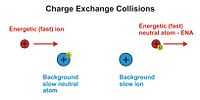
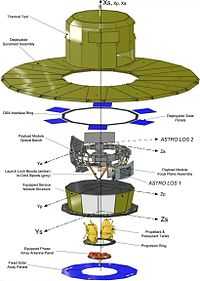
"The sensors on the IBEX spacecraft are able to detect energetic neutral atoms (ENAs) at a variety of energy levels."[24]
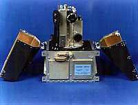
"The satellite's payload consists of two energetic neutral atom (ENA) imagers, IBEX-Hi and IBEX-Lo. Each of these sensors consists of a collimator that limits their fields-of-view, a conversion surface to convert neutral hydrogen and oxygen into ions, an electrostatic analyzer (ESA) to suppress ultraviolet light and to select ions of a specific energy range, and a detector to count particles and identify the type of each ion."[25]
"IBEX–Lo can detect particles with energies ranging from 10 electron–volts to 2,000 electron–volts (0.01 keV to 2 keV) in 8 separate energy bands. IBEX–Hi can detect particles with energies ranging from 300 electron–volts to 6,000 electron–volts (.3 keV to 6 keV) in 6 separate energy bands. ... Looking across the entire sky, interactions occurring at the edge of our Solar System produce ENAs at different energy levels and in different amounts, depending on the process."[24]
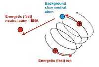
"Proton–hydrogen charge-exchange collisions [such as those shown at right] are often the most important process in space plasma because hydrogen is the most abundant constituent of both plasmas and background gases and hydrogen charge-exchange occurs at very high velocities involving little exchange of momentum."[26]
"Energetic neutral atoms (ENA), emitted from the magnetosphere with energies of ∼50 keV, have been measured with solid-state detectors on the IMP 7/8 and ISEE 1 spacecraft. The ENA are produced when singly charged trapped ions collide with the exospheric neutral hydrogen geocorona and the energetic ions are neutralized by charge exchange."[27]
"The IMAGE mission ... High Energy Neutral Atom imager (HENA) ... images [ENAs] at energies between 10 and 60 keV/nucleon [to] reveal the distribution and the evolution of energetic [ions, including protons] as they are injected into the ring current during geomagnetic storms, drift about the Earth on both open and closed drift paths, and decay through charge exchange to pre‐storm levels."[28]
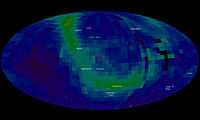
"In 2009, NASA's Interstellar Boundary Explorer (IBEX) mission science team constructed the first-ever all-sky map [at right] of the interactions occurring at the edge of the solar system, where the sun's influence diminishes and interacts with the interstellar medium. A 2013 paper provides a new explanation for a giant ribbon of energetic neutral atoms – shown here in light green and blue -- streaming in from that boundary."[29]
"[T]he boundary at the edge of our heliosphere where material streaming out from the sun interacts with the galactic material ... emits no light and no conventional telescope can see it. However, particles from inside the solar system bounce off this boundary and neutral atoms from that collision stream inward. Those particles can be observed by instruments on NASA’s Interstellar Boundary Explorer (IBEX). Since those atoms act as fingerprints for the boundary from which they came, IBEX can map that boundary in a way never before done. In 2009, IBEX saw something in that map that no one could explain: a vast ribbon dancing across this boundary that produced many more energetic neutral atoms than the surrounding areas."[29]
""What we are learning with IBEX is that the interaction between the sun's magnetic fields and the galactic magnetic field is much more complicated than we previously thought," says Eric Christian, the mission scientist for IBEX at NASA's Goddard Space Flight Center in Greenbelt, Md. "By modifying an earlier model, this paper provides the best explanation so far for the ribbon IBEX is seeing.""[29]
Electrons
The Energetic Particles Detector (EPD) aboard the Galileo Orbiter is "designed to measure the numbers and energies of ... electrons whose energies exceed about 20 keV ... The EPD [can] also measure the direction of travel of [electrons] ... The EPD [uses] silicon solid state detectors and a time-of-flight detector system to measure changes in the energetic [electron] population at Jupiter as a function of position and time."[30]
"[The] two bi-directional, solid-state detector telescopes [are] mounted on a platform which [is] rotated by a stepper motor into one of eight positions. This rotation of the platform. combined with the spinning of the orbiter in a plane perpendicular to the platform rotation, [permits] a 4-pi [or 4π] steradian coverage of incoming [electrons]. The forward (0 degree) ends of the two telescopes [have] an unobstructed view over the [4π] sphere or [can] be positioned behind a shield which not only [prevents] the entrance of incoming radiation, but [contains] a source, thus allowing background corrections and in-flight calibrations to be made. ... The 0 degree end of the [Low-Energy Magnetospheric Measurements System] LEMMS [uses] magnetic deflection to separate incoming electrons and ions. The 180 degree end [uses] absorbers in combination with the detectors to provide measurements of higher-energy electrons ... The LEMMS [provides] measurements of electrons from 15 keV to greater than 11 MeV ... in 32 rate channels."[9]
"The electron reflectometer (ER) [aboard the Lunar Prospector determines] the location and strength of magnetic fields from the energy spectrum and direction of electrons. The instrument [measures] the pitch angles of solar wind electrons reflected from the Moon by lunar magnetic fields. Stronger local magnetic fields can reflect electrons with larger pitch angles. Field strengths as small as 0.01 [nanotesla] nT could be measured with a spatial accuracy of about {3 km (1.9 mi) at the lunar surface. ... The ER ... [is] located at the end of one of the three radial science booms on [the] Lunar Prospector."[22]
Positrons
"[P]ositron astronomy results ... have been obtained using the INTEGRAL spectrometer SPI".[31]
The positrons are not directly observed by the INTEGRAL space telescope, but "the 511 keV positron annihilation emission is".[31]
Neutrinos
"The Extreme Universe Space Observatory (EUSO) is the first Space mission concept devoted to the investigation of cosmic rays and neutrinos of extreme energy (E > 5×10¹⁹
eV). Using the Earth's atmosphere as a giant detector, the detection is performed by looking at the streak of fluorescence produced when such a particle interacts with the Earth's atmosphere."[32]
Gamma rays
"AGILE (Astro‐rivelatore Gamma a Immagini LEggero) is an X-ray and Gamma ray astronomical satellite of the Italian Space Agency (ASI). [The] AGILE mission is ... to [observe] Gamma-Ray sources in the universe. ... AGILE’s instrumentation combines a gamma-ray imager (GRID) (sensitive in the energy range 30 MeV-50 GeV), a hard X-ray imager and monitor: Super- AGILE (sensitive in the range 18-60 KeV), a calorimeter (sensitive in the range 350 KeV-100 MeV) (MCAL), and an anticoincidence system (AC), based on plastic scintillator. AGILE was successfully launched on [April 23,] 2007".[33]
X-rays
“The SOLar RADiation satellite program (SOLRAD) was conceived in the late 1950s to study the Sun's effects on Earth, particularly during periods of heightened solar activity.[34] Solrad 1 is launched on June 22, 1960, aboard a Thor Able from Cape Canaveral at 1:54 a.m. EDT. As the world's first orbiting astronomical observatory, Solrad 1 determined that radio fade-outs were caused by solar X-ray emissions.[34]"[35]
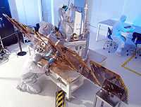
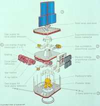
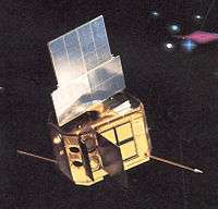
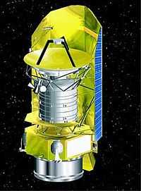
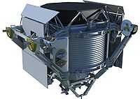
At left is an exploded view of the European X-ray Observatory Satellite (EXOSAT).
"This European Space Agency (ESA) satellite for direct-pointing and lunar-occultation observation of X-ray sources beyond the solar system was launched into a highly eccentric orbit (apogee 200,000 km, perigee 500 km) almost perpendicular to that of the moon on May 26, 1983. The instrumentation includes two low-energy imaging telescopes (LEIT) with Wolter I X-ray optics (for the 0.04-2 keV energy range), a medium-energy experiment using Ar/CO2 and Xe/CO2 detectors (for 1.5-50 keV), a Xe/He gas scintillation spectrometer (GSPC) (covering 2-80 keV), and a reprogrammable onboard data-processing computer. Exosat is capable of observing an object (in the direct-pointing mode) for up to 80 hours and of locating sources to within at least 10 arcsec with the LEIT and about 2 arcsec with GSPC.[36]"[37]
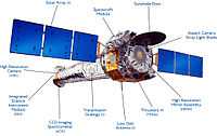
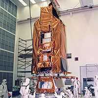
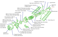
At lower right is a pictorial diagram for the Chandra X-ray Observatory, NSSDC ID 1999-040B, of some of the major satellite systems.
"The Chandra X-ray Observatory (formerly the Advanced X-ray Astrophysics Facility, or AXAF) was built around a high-resolution grazing incidence X-ray telescope which made observations in the 0.09 to 10.0 keV energy range."[38]
"The spacecraft has a cone-shaped body with an octagonal structure surrounding the wide end. Two solar panel wings extend from opposite sides of the structure. The main opening is at the wide end covered by a sunshade door with a contamination cover. An aspect camera and stray light shade are mounted near the opening and two low-gain antennas and two fine Sun sensors are affixed to the outside structure. Thermal control is maintained by a radiator, insulators, heaters, and thermostats. Power generated by the solar panels is stored in three banks of batteries."[38]
"The X-ray telescope consists of four nested paraboloid-hyperboloid X-ray mirror pairs, arranged in concentric cylinders within the cone. The four instruments are located near the focus at the narrow end of the cone: the High Resolution Camera (HRC), the CCD Imaging Spectrometer (ACIS), High Energy Transmission Grating Spectrometer (HETGS), and the Low Energy Transmission Grating (LETG)."[38]
Ultraviolets
"The Far Ultraviolet Spectroscopic Explorer (FUSE) ... detected light in the far ultraviolet portion of the electromagnetic spectrum, between 90.5-119.5 nanometres, which is mostly unobservable by other telescopes. Its primary mission was to characterize universal deuterium in an effort to learn about the stellar processing times of deuterium left over from the Big Bang. ... [T]he ... telescope comprises four individual mirrors. Each of the four mirrors is a 39-by-35 cm (15.4-by-13.8 in) off-axis parabola. Two mirror segments are coated with silicon carbide for reflectivity at the shortest ultraviolet wavelengths, and two mirror segments are coated with lithium fluoride over aluminum that reflects better at longer wavelengths. ... Each mirror has a corresponding astigmatism-corrected, holographically-ruled diffraction grating, each one on a curved substrate so as to produce four 1.65 m (5.4 ft) Rowland circle spectrographs. The dispersed ultraviolet light is detected by two microchannel plate intensified double delay-line detectors, whose surfaces are curved to match the curvature of the focal plane.[39]"[40]
Opticals
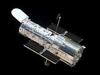
The Hubble Space Telescope is an excellent example of a radiation satellite designed for more than one purpose: the various astronomies of optical astronomy.
“Hubble's four main instruments observe in the near ultraviolet, visible, and near infrared. ... Hubble's Ultra-Deep Field image, for instance, is the most detailed visible-light image ever made of the universe's most distant objects. ... Hubble is the only telescope designed to be serviced in space by astronauts. ... Optically, the HST is a Cassegrain reflector of Ritchey-Chrétien design, as are most large professional telescopes. This design, with two hyperbolic mirrors, is known for good imaging performance over a wide field of view, with the disadvantage that the mirrors have shapes that are hard to fabricate and test. The mirror and optical systems of the telescope determine the final performance, and they were designed to exacting specifications.”[41]
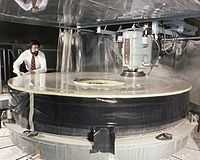
“Optical telescopes typically have mirrors polished to an accuracy of about a tenth of the wavelength of visible light, but the Space Telescope was to be used for observations from the visible through the ultraviolet (shorter wavelengths) and was specified to be diffraction limited to take full advantage of the space environment. Therefore its mirror needed to be polished to an accuracy of 10 nanometers, or about 1/65 of the wavelength of red light.[42] On the long wavelength end, the OTA was not designed with optimum IR performance in mind — for example, the mirrors are kept at stable (and warm, about 15 °C) temperatures by heaters. This limits Hubble's performance as an infrared telescope.[43]”[41]
The HST is an optical astronomy telescope that “incorporated a set of 48 filters isolating spectral lines of particular astrophysical interest. The instrument contained eight charge-coupled device (CCD) chips divided between two cameras, each using four CCDs. The "wide field camera" (WFC) covered a large angular field at the expense of resolution, while the "planetary camera" (PC) took images at a longer effective focal length than the WF chips, giving it a greater magnification.[44] The GHRS was a spectrograph designed to operate in the ultraviolet. It was built by the Goddard Space Flight Center and could achieve a spectral resolution of 90,000.[45] Also optimized for ultraviolet observations were the FOC and FOS, which were capable of the highest spatial resolution of any instruments on Hubble. Rather than CCDs these three instruments used photon-counting digicons as their detectors. ... The final instrument was the HSP, designed and built at the University of Wisconsin–Madison. It was optimized for visible and ultraviolet light observations of variable stars and other astronomical objects varying in brightness. It could take up to 100,000 measurements per second with a photometric accuracy of about 2% or better.[46]”[41]
“HST's guidance system can also be used as a scientific instrument. Its three Fine Guidance Sensors (FGS) are primarily used to keep the telescope accurately pointed during an observation, but can also be used to carry out extremely accurate astrometry; measurements accurate to within 0.0003 arcseconds have been achieved.[47]”[41]
Visuals
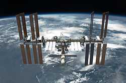
An STS-134 crew member on the space shuttle Endeavor photographed the International Space Station shown at right. The photograph was taken after the station and shuttle began their post-undocking relative separation.
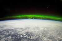
At right is a natural color photograph of the Aurora Borealis or northern lights and the Manicouagan Impact Crater reservoir (foreground) in Quebec, Canada. They are featured in this photograph taken by astronaut Donald R. Pettit, Expedition Six NASA ISS science officer, on board the International Space Station (ISS).
Violets
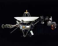

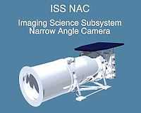
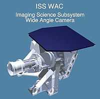
The scan platform of Voyager 1 and 2 comprises: the Infrared Interferometer Spectrometer (IRIS) (largest camera at right) in the image at left; the Ultraviolet Spectrometer (UVS) to the right of the UVS; the two Imaging Science Subsystem (ISS) vidicon cameras to the left of the UVS; and the Photopolarimeter System (PPS) barely visible under the ISS.
At right is an image of the spectral range of the Violet filter (50 to 400 nm)[48] on the Imaging Science System aboard the Voyager 1 and Voyager 2 Spacecraft, as defined by the instrument descriptions of the Narrow Angle Camera and Wide Angle Camera.
Blues
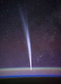
Comet Lovejoy is visible near Earth's horizon in this nighttime image at right photographed by NASA astronaut Dan Burbank, Expedition 30 commander, onboard the International Space Station on Dec. 22, 2011.
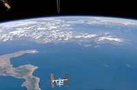
Pictured here at right the ISS is visible in front the Ionian Sea. The boot of Italy is visible on the left, while the western coastlines of Greece and Albania stretch across the top. The dorsal fin of the upside-down shuttle orbiter pokes into the very top of the image.
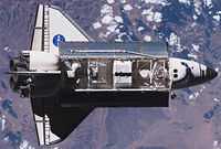
Endeavour, shown at left, is contributing toward space station construction by delivering a third starboard truss segment, S5, and supplies inside the SPACEHAB module (in the center of the bay) and the external stowage platform 3.
Cyans
“In January 1986, the Voyager 2 spacecraft flew by Uranus at a minimal distance of 107,100 km[49] providing the first close-up images and spectra of its atmosphere. They generally confirmed that the atmosphere was made of mainly hydrogen and helium with around 2% methane.[50] The atmosphere appeared highly transparent and lacking thick stratospheric and tropospheric hazes. Only a limited number of discrete clouds were observed.[51]”[52]
To produce 3D images of the Sun, the STEREO spacecraft [at right] take images in red and cyan.
Greens
The Cassini Orbiter spacecraft that is in orbit around Saturn has two science telescopes observing in the green. The Imaging Science Subsystem (ISS) has a narrow angle camera (NAC) and a wide angle camera (WAC). The NAC uses a reflecting telescope and the WAC uses a refractor. The NAC on Cassini has a green filter centered at 568 nanometers. The WAC has a 567 nm centroid.[53] Overall the camera observes a wavelength range of 200-1100 nm and has 24 filters [on two wheels] with a 6.0 microradians per pixel angular resolution.[54]
The wide angle camera detects a wavelength range from 380-1100 nm using 18 filters [on two wheels] and has a 60 microradians per pixel angular resolution.[54]
"The Visual and Infrared Mapping Spectrometer (VIMS) is a pair of imaging grating spectrometers designed to measure reflected and emitted radiation from atmospheres, rings, and surfaces over wavelengths from 0.35 to 5.1 micrometers to determine their compositions, temperatures, and structures. ... The visible channel (VIMS-V) is an opto-mechanical assembly designed to produce multispectral images in the visible range. It consists of a Shafer telescope, a holographic spectrometer grating, and a silicon CCD area array focal plane detector cooled to its required temperature by a passive radiator. The VIMS-V will be configured as a "pushbroom" imager, which means that the optical instrument's IFOV is an entire line of pixels. This is scanned over the scene with a single-axis scanning mirror to produce a series of contiguous rows, which together form a two-dimensional image. ... The visible channel has 96 channels covering the wavelength range from 0.35 to 1.07 µm."[55]
The Hubble Space Telescope has used three cameras to capture green images: the wide field planetary camera 1 (PC-1), the wide field planetary camera 2 (PC-2), and the wide field camera 3 (WCF3).
The Galileo spacecraft uses a 559 nm green filter.
The Rosetta Spacecraft has two instruments aboard that use green astronomy: the Optical, Spectroscopic, and Infrared Remote Imaging System (OSIRIS) and the Visible and Infrared Thermal Imaging Spectrometer (VIRTIS).
For OSIRIS, "[t]he camera system has a narrow-angle lens (700 mm) and a wide-angle lens (140 mm), with a 2048x2048 pixel [charge-coupled device] CCD chip."[56]"[57]
"The Visible and IR spectrometer is able to make pictures of the core in the IR and also search for IR spectra of molecules in the coma. The detection is done by a mercury cadmium teluride array for IR and with a CCD chip for the Visible range. ... improved versions were used for Dawn and Venus express.[58]"[57]
The Dawn spacecraft has onboard a framing camera (FC) with a refractive optical system and an 8-position filter wheel of a panchromatic (clear filter) and seven narrow band filters.[59] "The visual and infrared spectrometer (VIR) ... [has] an array of HgCdTe photodiodes cooled to about 70K spans the spectrum from 0.95 to 5.0 µm.[60][61]"[59] The green filter aboard Dawn in the FC has a central wavelength of 555 nm.[62] The VIR on Dawn has a green filter centered at 563 nm.[63]
"VMC: The Venus Monitoring Camera is a wide-angle, multi-channel CCD. The VMC is designed for global imaging of the planet.[64] It operates in the visible, ultraviolet, and near infrared spectral ranges, and maps surface brightness distribution searching for volcanic activity, monitoring airglow, studying the distribution of unknown ultraviolet absorbing phenomenon at the cloud-tops, and making other science observations."[65]
"VIRTIS: The "Visible and Infrared Thermal Imaging Spectrometer" (VIRTIS) is an imaging spectrometer that observes in the near-ultraviolet, visible, and infrared parts of the electromagnetic spectrum. It will analyze all layers of the atmosphere, surface temperature and surface/atmosphere interaction phenomena."[65]
Yellows
Composite images of the Sahara, a large yellow feature on Earth in the northern third of Africa, are mostly from the MODIS imager on board the Terra satellite.
Oranges
LandSat 7 is one of the most recent of the LandSat series of Earth observing satellites. It produced an orange astronomy image of the Namib Desert.
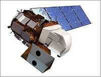
Landsat 8 is a "collaboration between NASA and the US Geological Survey to obtain measurements of the Earth's radiation in the visible, near-infrared, short wave infrared, and thermal infrared."[66] The satellite is referred to as the Landsat Data Continuity Mission (LDCM).[67]
"The LDCM spacecraft uses a nadir-pointing three-axis stabilized platform (zero momentum biased) ... The ADCS (Attitude Determination and Control Subsystem) employs six reaction wheels and three torque rods as actuators. Attitude is sensed with three precision star trackers (2 of 3 star trackers are active), a redundant SIRU (Scalable Inertial Reference Unit), twelve coarse sun sensors, redundant GPS receivers (Viceroy), and two TAMs (Three Axis Magnetometers)."[67]
"Attitude control error (3σ): ≤ 30 µrad; Attitude knowledge error (3σ): ≤ 46 µrad; Attitude knowledge stability (3σ): ≤ 0.12 µrad in 2.5 seconds; ≤ 1.45 µrad in 30 seconds; [and] Slew time: 180º any axis: ≤ 14 minutes, including settling; 15º roll: ≤ 4.5 minutes, including settling."[67]
The "spacecraft pointing capability [allows] the calibration of the OLI using the sun (roughly weekly), the moon (monthly), stars (during commissioning) and the Earth (at 90° from normal orientation, a.k.a., side slither) quarterly. The solar calibration [is] used for OLI absolute and relative calibration, the moon for trending the stability of the OLI response, the stars [are] used for Line of Sight determination and the side slither [is] an alternate OLI and relative gain determination methodology."[67]
"C&DH (Command & Data Handling) subsystem: The C&DH subsystem uses a standard cPCI backplane RAD750 CPU. The MIL-STD-1553B data bus is used for onboard ADCS, C&DH functions and instrument communications. The SSR (Solid State Recorder) provides a storage capacity of 4 Tbit @ BOL and 3.1 Tbit @ EOL. The C&DH subsystem provides the mission data interfaces between instruments, the SSR, and the X-band transmitter. The C&DH subsystem consists of an IEM (Integrated Electronics Module), a PIE (Payload Interface Electronics), the SSR, and two OCXO (Oven Controlled Crystal Oscillators)."[67]
"TCS (Thermal Control Subsystem): The TCS uses standard Kapton etched-foil strip heaters. In general, a passive, cold-biased system is used for the spacecraft. Multi-layer insulation on spacecraft and payload as required. A deep space view is provided for the instrument radiators."[67]
"EPS (Electric Power Subsystem): The EPS consists of a single deployable solar array with single-axis articulation capability and with a stepping gimbal. Triple-junction solar cells are being used providing a power of 4300 W @ EOL. The NiH2 battery has a capacity of 125 Ah. Use of unregulated 22-36 V power bus."[67]
"The onboard propulsion subsystem provides a total velocity change of ΔV = 334 m/s using eight 22 N thrusters for insertion error correction, altitude adjustments, attitude recovery, EOL disposal, and other operational maintenance as necessary."[67]
"RF communications: Earth coverage antennas are being used for all data links. The X-band downlink uses lossless compression and spectral filtering. The payload data rate is 440 Mbit/s. The X-band RF system consists of the X-band transmitter, TWTA (Travelling Wave Tube Amplifier), DSN (Deep Space Network) filter, and an ECA (Earth Coverage Antenna). The serial data output is set at 440.825 Mbit/s and is up-converted to 8200.5 MHz. The TWTA amplifies the signal such that the output of the DSN filter is 62 W. The DSN filter maintains the signal’s spectral compliance. An ECA provides nadir full simultaneous coverage, utilizing 120º half-power beamwidth, for all in view ground sites below the spacecraft's current position with no gimbal or actuation system. The system is designed to handle up to 35 separate ground contacts per day as forecasted by the DRC-16 (Design Reference Case-16)."[67]
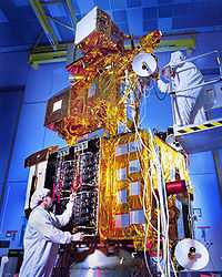
The second image at left is a view of the deployed LDCM spacecraft showing the calibration ports of the TIRS and OLI instruments.
The Operational Land Imager (OLI) is multispectral and of moderate resolution. "An edge response slope is ... specified for the image date from each [of nine] spectral band. The edge response is defined as the normalized response of the image data to a sharp edge as expressed in a Level 1R VDP (Validation Data Product). An edge response slope of 0.027 is required for bands 1 through 7, a slope of 0.054 is required for the panchromatic band, band 8, and a slope of 0.006 for the cirrus band, band 9."[67]
The nine bands are
- New Deep Blue 433-453 nm,
- Blue 450-515 nm,
- Green 525-600 nm,
- Red 630-680 nm,
- NIR 845-885 nm,
- SWIR 2 1560-1660 nm,
- SWIR 3 2100-2300 nm,
- PAN 500-680 nm (for image sharpening), and
- SWIR 1360-1390 nm.[67]
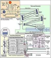
"The OLI calibration subsystem [at lower right] consists of two solar diffusers (a working and a pristine), and a shutter. When positioned so that the sun enters the solar lightshade, the diffusers reflect light diffusely into the instruments aperture and provide a full system full aperture calibration. The shutter, when closed, provides a dark reference. In addition, two stim lamp assemblies are located at the front aperture stop. Each lamp assembly contains three lamps (per redundant configuration) that are operated at constant current and monitored by a silicon photodiode. The lamp signal goes through the full telescope system. Additionally, the OLI focal plane [includes] masked HgCdTe detectors, that is, detectors that [are] blocked from seeing the Earth’s radiance"[67]
The Thermal Infrared Sensor (TIRS) "is a QWIP (Quantum Well Infrared Photodetector) based instrument intended to supplement the observations of the OLI instrument. The TIRS instrument is a TIR (Thermal Infrared) imager operating in the pushbroom mode with two IR channels: 10.8 µm and 12 µm. The two spectral bands are achieved through interference filters that cover the FPA (Focal Plane Assembly)."[67]
"The imaging telescope [for the TIRS] is a 4-element refractive lens system. A scene select mechanism (SSM) rotates a scene mirror (SM) to change the field of regard from a nadir Earth view to either an on-board blackbody calibrator or a deep space view. The blackbody is a full aperture calibrator whose temperature may be varied from 270 to 330 K."[67]
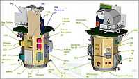
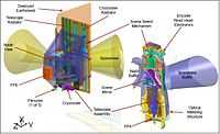
At lowest left are two orientations for a schematic view of the TIRS instrument internal assembly. "The scene select mechanism rotates the field of regard from the Earth view to either the space view or to the on-board calibrator. The right side provides some detail of optical system showing the 4-element lens, a cut-away view of the [Scene Mirror] SM and the thermal strap connecting the [Focal Plane Assembly] FPA to the cryocooler cold tip."[67]
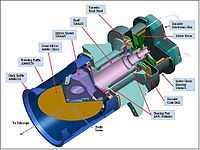
At lowest right is a cutaway view of the Scene Select Mechanism (SSM) of the TIRS. The SSM ... is a single axis, direct drive mechanism which rotates a 207 mm scene mirror from the nadir science position to the 2 calibration positions twice per orbit. It provides pointing knowledge and stability to ~10 µradians. The SSM can be driven in either direction for unlimited rotations. The rotating mirror is dynamically balanced over the spin axis, and does not require launch locking."[67]
"The design of the SSM is straightforward; it is a single axis rotational mechanism. The operational cadence [is] to hold the scene mirror stationary for ~40 minutes staring at nadir, rotate 120º to the space view aperture and stare for 30 seconds, rotate 120º to the internal blackbody and stare for 30 seconds and then rotate the mirror to the back to nadir. Then the entire process [starts] again. The mechanism [operates] all of the time, or [has] a 100% duty cycle. Since LDCM/TIRS [is] in a highly-inclined polar orbit, the general idea [is] to calibrate twice per orbit while over the poles."[67]
Reds
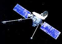
Mariner 10, at right, made a true color image of Mercury that shows its reddish color.
"The equipment consisted of two spherical (150 mm diameter) Cassegrain telescopes with eight filters, each attached to a GEC 1 inch vidicon tube camera (1500 mm focal length and 0.5 degree field of view) for narrow-angle photography. An auxiliary optical system mounted on each camera provided wide-angle (62 mm focal length, 11 x 14 degree field of view) photography by moving a mirror on a filter wheel to a position in the optical path. Exposure time ranged from 3 ms to 12 s, and each camera took a picture every 42 s. The TV picture consisted of 700 scan lines with 832 picture elements per line, which were digitally coded into eight-bit words for transmission. There were eight filter wheel positions: (1) wide-angle image relay mirror; (2) blue bandpass; (3) UV polarizing; (4) minus UV high pass; (5) clear; (6) UV bandpass; (7) defocusing lens (for calibration); and, (8) yellow bandpass."[68]
Infrareds
The European Space Agency's Herschel Space Observatory has aboard the Photodetector Array Camera and Spectrometer (PACS). "The camera operates in three bands centred on 70, 100, and 160 μm, respectively, and the spectrometer covers the wavelength range between 51 and 220 μm."[69]
Submillimeters
The Submillimeter Wave Astronomy Satellite "is a NASA Small Explorer Project (SMEX) designed to study the chemical composition of interstellar gas clouds."[70]
Microwaves
The COBE is launched into Earth orbit on November 18, 1989. The WMAP is launched on June 30, 2001, into orbit at the Lagrange 2 location. Both satellites have aboard detectors designed to perform microwave astronomy, as these are limited to only the microwave band.
The Gravity Recovery and Climate Experiment (GRACE) "mission uses a microwave ranging system to accurately measure changes in the speed and distance between two identical spacecraft flying in a polar orbit about 220 kilometers (140 mi) apart, 500 kilometers (310 mi) above Earth. The ranging system is sensitive enough to detect separation changes as small as 10 micrometres (approximately one-tenth the width of a human hair) over a distance of 220 kilometers.[71]"[72]
"As the twin GRACE satellites circle the globe 15 times a day, they sense minute variations in Earth's gravitational pull. When the first satellite passes over a region of slightly stronger gravity, a gravity anomaly, it is pulled slightly ahead of the trailing satellite. This causes the distance between the satellites to increase. The first spacecraft then passes the anomaly, and slows down again; meanwhile the following spacecraft accelerates, then decelerates over the same point."[72]
"The basic scientific goal of the Planck mission is to measure [cosmic microwave background] CMB anisotropies at all angular scales larger than 10 arcminutes over the entire sky with a precision of ~2 parts per million. The model payload consists of a 1.5 meter off-axis telescope with two focal plane arrays of detectors sharing the focal plane. Low frequencies will be covered by 56 tuned radio receivers sensitive to 30-100 GHz, while high frequencies will be covered by 56 bolometers sensitive to 100-850 GHz."[73]
Radars
"[N]umerous airborne and spacecraft radars have mapped the entire planet, for various purposes. One example is the Shuttle Radar Topography Mission, which mapped the entire Earth at 30 m resolution."[74]
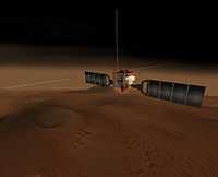
"The Mars Express mission carries a ground-penetrating radar."[74]
Radios
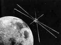
“Explorer 49 [is] a 328 kilogram satellite launched on June 10, 1973 for longwave radio astronomy research. It had four 230-meter long X-shaped antenna elements, which made it one of the largest spacecraft ever built. ... Explorer 49 was placed into lunar orbit to provide radio astronomical measurements of the planets, the sun, and the galaxy over the frequency range of 25 kHz to 13.1 MHz.”[75]
Superluminals
"The Alpha Magnetic Spectrometer device AMS-02, recently mounted on the International Space Station uses a RICH detector in combination with other devices to analyze cosmic rays."[76]
Research
Hypothesis:
- The use of satellites should provide ten times the information as sounding rockets or balloons.
Control groups

The findings demonstrate a statistically systematic change from the status quo or the control group.
“In the design of experiments, treatments [or special properties or characteristics] are applied to [or observed in] experimental units in the treatment group(s).[77] In comparative experiments, members of the complementary group, the control group, receive either no treatment or a standard treatment.[78]"[79]
A control group for a radiation satellite would contain
- a radiation astronomy telescope,
- a two-way communication system,
- a positional locator,
- an orientation propulsion system, and
- power supplies and energy sources for all components.
A control group for radiation astronomy satellites may include an ideal or rigorously stable orbit so that the satellite observes the radiation at or to a much higher resolution than an Earth-based ground-level observatory is capable of.
Proof of concept
Def. a “short and/or incomplete realization of a certain method or idea to demonstrate its feasibility"[80] is called a proof of concept.
Def. evidence that demonstrates that a concept is possible is called proof of concept.
The proof-of-concept structure consists of
- background,
- procedures,
- findings, and
- interpretation.[81]
Proof of technology
"[T]he objective of a proof of technology is to determine the solution to some technical problem, such as how two systems might be integrated or that a certain throughput can be achieved with a given configuration."[82]
Def.
- "[a]n original object or form which is a basis for other objects, forms, or for its models and generalizations",[83]
- "[a]n early sample or model built to test a concept or process",[83] or
- "[a]n instance of a category or a concept that combines its most representative attributes"[83] is called a prototype.
Def. "[t]o test something using the conditions that it was designed to operate under, especially out in the real world instead of in a laboratory or workshop"[84] is called "field-test", or a field test.
A "proof-of-technology prototype ... typically implements one critical scenario to exercise or stress the highest-priority requirements."[85]
"[A] proof-of-technology test demonstrates the system can be used"[86].
"The strongest proof of technology performance is based on consistency among multiple lines of evidence, all pointing to similar levels of risk reduction."[87]
See also
References
- 1 2 Gerald A. Ouellette (June 1967). "Development of a Catalogue of Galactic X-Ray Sources". The Astronomical Journal 72 (5): 597-600. doi:10.1086/110278.
- ↑ Ed Grayzeck (August 16, 2013). "Gaia". Washington, DC USA: National Space Science Data Center, NASA. Retrieved 2014-01-07.
- ↑ C. Carreau (December 19, 2013). "ESA PR 44-2013: Liftoff for ESA's Billion-Star Surveyor". European Space Agency. Retrieved 2014-01-07.
- 1 2 3 Harlan E. Spence (August 16, 2013). "Van Allen Probe A (RBSP-A)". Washington, DC USA: National Space Science Data Center, NASA. Retrieved 2014-01-07.
- ↑ Louis J. Lanzerotti (August 16, 2013). "Van Allen Probe A (RBSP-A)". Washington, DC USA: National Space Science Data Center, NASA. Retrieved 2014-01-07.
- ↑ Edwin V. Bell, II (August 16, 2013). "Van Allen Probe A (RBSP-A)". Washington, DC USA: National Space Science Data Center, NASA. Retrieved 2014-01-07.
- 1 2 3 Richard C. Elphic, Sarah Noble, and P. Butler Hine III (September 7, 2013). "Lunar Atmosphere and Dust Environment Explorer (LADEE)". Washington, DC USA: National Space Science Data Center, NASA. Retrieved 2014-01-07.
- ↑ Lester Haines (July 28, 2011). "Jupiter spacecraft mounted atop bloody big rocket Juno to ride the thrust of five mighty strap-ons". United Kingdom: The Register. Retrieved 2014-01-08.
- 1 2 3 David R. Williams (August 16, 2013). "Juno". Washington, DC USA: National Space Science Data Center, NASA. Retrieved 2014-01-08.
- 1 2 3 Dieter K. Bilitza (August 16, 2013). "Aeronomy of Ice in the Mesosphere". Washington, DC USA: National Space Science Data Center, NASA. Retrieved 2014-01-08.
- ↑ Mark Hervig (August 16, 2013). "Aeronomy of Ice in the Mesosphere". Washington, DC USA: National Space Science Data Center, NASA. Retrieved 2014-01-08.
- ↑ Cora E. Randall (August 16, 2013). "Aeronomy of Ice in the Mesosphere". Washington, DC USA: National Space Science Data Center, NASA. Retrieved 2014-01-08.
- ↑ Mihaly Horanyi (August 16, 2013). "Aeronomy of Ice in the Mesosphere". Washington, DC USA: National Space Science Data Center, NASA. Retrieved 2014-01-08.
- ↑ "satellite, In: Wiktionary". San Francisco, California: Wikimedia Foundation, Inc. June 19, 2012. Retrieved 2012-08-10.
- 1 2 3 4 5 Sheldon (April 29, 2011). "Materials: Out of This World". Washington DC USA: NASA News. Retrieved 2014-01-08.
- 1 2 3 Rosemary Sullivant (May 31, 2011). "Aquarius Studying Our Salty Seas From Space". Pasadena, California USA: Jet Propulsion Laboratory, NASA. Retrieved 2014-01-08.
- 1 2 3 4 5 6 William Harwood (October 6, 2006). "Shuttles to resume nighttime launches; Atlantis damaged". Spaceflight Now. Retrieved 2013-10-29.
- 1 2 "Alpha Magnetic Spectrometer, In: Wikipedia". San Francisco, California: Wikimedia Foundation, Inc. August 4, 2012. Retrieved 2012-08-10.
- ↑ "Alpha Magnetic Spectrometer claims huge cosmic ray haul". BBC. 25 July 2012. Retrieved 26 July 2012.
- 1 2 3 "Payload for Antimatter Matter Exploration and Light-nuclei Astrophysics, In: Wikipedia". San Francisco, California: Wikimedia Foundation, Inc. February 1, 2012. Retrieved 2012-08-10.
- ↑ P.Picozza et al., "Launch of the space experiment PAMELA", http://arxiv.org/abs/0708.1808
- 1 2 "Lunar Prospector, In: Wikipedia". San Francisco, California: Wikimedia Foundation, Inc. August 12, 2012. Retrieved 2012-08-12.
- 1 2 Mike Gruntman. "Charge Exchange Diagrams". Energetic Neutral Atoms Tutorial. Retrieved 2009-10-27.
- 1 2 Dave McComas and Lindsay Bartolone (May 10, 2012). "IBEX: Interstellar Boundary Explorer". San Antonio, Texas USA: NASA Southwest Research Institute. Retrieved 2012-08-11.
- ↑ "Interstellar Boundary Explorer, In: Wikipedia". San Francisco, California: Wikimedia Foundation, Inc. May 13, 2012. Retrieved 2012-08-11.
- ↑ "Energetic neutral atom, In: Wikipedia". San Francisco, California: Wikimedia Foundation, Inc. August 4, 2012. Retrieved 2012-08-12.
- ↑ E. C. Roelof, D. G. Mitchell, D. J. Williams (1985). "Energetic neutral atoms (E ∼ 50 keV) from the ring current: IMP 7/8 and ISEE 1". Journal of Geophysical Research 90 (A11): 10,991-11,008. doi:10.1029/JA090iA11p10991. http://www.agu.org/pubs/crossref/1985/JA090iA11p10991.shtml. Retrieved 2012-08-12.
- ↑ D. G. Mitchell, K. C. Hsieh, C. C. Curtis, D. C. Hamilton, H. D. Voes, E. C, Roelof, P. C:son-Brandt (2001). "Imaging two geomagnetic storms in energetic neutral atoms". Geophysical Research Letters 28 (6): 1151-4. doi:10.1029/2000GL012395. http://www.agu.org/pubs/crossref/2001/2000GL012395.shtml. Retrieved 2012-08-12.
- 1 2 3 Karen C. Fox (February 5, 2013). "A Major Step Forward in Explaining the Ribbon in Space Discovered by NASA’s IBEX Mission". Greenbelt, MD USA: NASA's Goddard Space Flight Center. Retrieved 2013-02-06.
- ↑ "Galileo (spacecraft), In: Wikipedia". San Francisco, California: Wikimedia Foundation, Inc. August 7, 2012. Retrieved 2012-08-11.
- 1 2 G. Weidenspointner, G.K. Skinner, P. Jean, J. Knödlseder, P. von Ballmoos, R. Diehl, A. Strong, B. Cordier, S. Schanne, C. Winkler (October 2008). "Positron astronomy with SPI/INTEGRAL". New Astronomy Reviews 52 (7-10): 454-6. doi:10.1016/j.newar.2008.06.019. http://www.sciencedirect.com/science/article/pii/S1387647308001164. Retrieved 2011-11-25.
- ↑ "Extreme Universe Space Observatory, In: Wikipedia". San Francisco, California: Wikimedia Foundation, Inc. July 21, 2012. Retrieved 2012-08-23.
- ↑ "AGILE (satellite), In: Wikipedia". San Francisco, California: Wikimedia Foundation, Inc. May 2, 2013. Retrieved 2013-05-09.
- 1 2 TD Calderwood. "Highlights of NRL's First 75 Years".
- ↑ "X-ray astronomy satellites, In: Wikipedia". San Francisco, California: Wikimedia Foundation, Inc. May 10, 2012. Retrieved 2012-08-10.
- ↑ Henry A. Hoff (August 1983). "EXOSAT - The new extrasolar X-ray observatory". Journal of the British Interplanetary Society (Space Chronicle) 36 (8): 363-7. http://md1.csa.com/partners/viewrecord.php?requester=gs&collection=TRD&recid=A8339971AH&q=&uid=788028604&setcookie=yes.
- ↑ Marshallsumter (September 8, 2009). "EXOSAT, In: Wikipedia". San Francisco, California: Wikimedia Foundation, Inc. Retrieved 2014-01-03.
- 1 2 3 Michael M. Harrington, Jeffrey S. McKenzie, and Fred S. Wojtalik (January 6, 2014). "Chandra X-ray Observatory". Washington, DC UASA: National Aeronautics and Space Administration. Retrieved 2014-01-06.
- ↑ D.J. Sahnow, et al. (1995-07-03). "The Far Ultraviolet Spectroscopic Explorer Mission". JHU.edu. Retrieved 2007-09-07.
- ↑ "Far Ultraviolet Spectroscopic Explorer, In: Wikipedia". San Francisco, California: Wikimedia Foundation, Inc. March 9, 2012. Retrieved 2012-06-26.
- 1 2 3 4 "Hubble Space Telescope, In: Wikipedia". San Francisco, California: Wikimedia Foundation, Inc. January 21, 2013. Retrieved 2013-01-22.
- ↑ "Hubble: The Case of the Single-Point Failure" (PDF). Science Magazine. 1990-08-17. Retrieved 2008-04-26.
- ↑ Robberto, M. and Sivaramakrishnan, A. and Bacinski, J.J. and Calzetti, D. and Krist, J.E. and MacKenty, J.W. and Piquero, J. and Stiavelli, M. (2000). "The Performance of HST as an Infrared Telescope" (PDF). Proc. SPIE 4013: 386–393. doi:10.1117/12.394037. http://www.stsci.edu/hst/wfc3/documents/published/spie4013386.pdf.
- ↑ Donald N.B. Hall, ed (1982). The Space Telescope Observatory. NASA. http://hdl.handle.net/2060/19820025420. 40 MB PDF file.
- ↑ Brandt J.C. et al. (1994). "The Goddard High Resolution Spectrograph: Instrument, goals, and science results". Publications of the Astronomical Society of the Pacific 106: 890–908. doi:10.1086/133457.
- ↑ Bless R.C., Walter L.E., White R.L. (1992), High Speed Photometer Instrument Handbook, v 3.0, STSci
- ↑ Benedict, G. Fritz; McArthur, Barbara E. (2005). D.W. Kurtz. ed. High-precision stellar parallaxes from Hubble Space Telescope fine guidance sensors, In: Transits of Venus: New Views of the Solar System and Galaxy. Cambridge University Press. pp. 333–46. http://adsabs.harvard.edu/abs/2005tvnv.conf..333B.
- ↑ M. Benesh and F. Jepsen (August 6, 1984). "SP-474 Voyager 1 and 2 Atlas of Six Saturnian Satellites Appendix A The Voyager Mission". Washington, DC USA: NASA. Retrieved 2013-04-01.
- ↑ Stone, E. C. (December 30, 1987). "The Voyager 2 Encounter with Uranus". Journal of Geophysical Research 92 (A13): 14,873–14,876. Bibcode 1987JGR....9214873S. doi:10.1029/JA092iA13p14873
- ↑ Fegley, Bruce Jr.; Gautier, Daniel; Owen, Tobias; Prinn, Ronald G. (1991). "Spectroscopy and chemistry of the atmosphere of Uranus". In Bergstrahl, Jay T.; Miner, Ellis D.; Matthews, Mildred Shapley (PDF). Uranus. University of Arizona Press. ISBN 978-0-8165-1208-9. OCLC 22625114.
- ↑ Smith, B. A.; Soderblom, L. A.; Beebe, A.; Bliss, D.; Boyce, J. M.; Brahic, A.; Briggs, G. A.; Brown, R. H. et al (4 July 1986). "Voyager 2 in the Uranian System: Imaging Science Results". Science 233 (4759): 43–64. Bibcode 1986Sci...233...43S. doi:10.1126/science.233.4759.43. PMID 17812889
- ↑ "Atmosphere of Uranus, In: Wikipedia". San Francisco, California: Wikimedia Foundation, Inc. July 3, 2012. Retrieved 2012-07-30.
- ↑ Carolyn C. Porco, Robert A. West, Steven Squyres, Alfred McEwen, Peter Thomas, Carl D. Murrays, Anthony Delgenio, Andrew P. Ingersoll, Torrence V. Johnson, Gerhard Neukumb, Joseph Veverka, Luke Dones, Andre Brahic, Joseph A. Burns, Vance Haemmerle, Benjamin Knowles, Douglas Dawson, Thomas Roatsch, Kevin Beurles and William Owen (December 2004). "Cassini Imaging Science: Instrument Characteristics and Anticipated Scientific Investigations at Saturn". Space Science Reviews 115 (1-4): 363-497. doi:10.1007/s11214-004-1456-7. http://www.ciclops.org/sci/docs/CassiniImagingScience.pdf. Retrieved 2013-01-26.
- 1 2 Carolyn C. Porco. "Cassini Solstice Mission Inside the Spacecraft". Pasadena, California USA: NASA/JPL. Retrieved 2013-01-26.
- ↑ Robert H. Brown. "VIMS Engineering Technical Write-up". Pasadena, California USA: NASA/JPL. Retrieved 2013-01-26.
- ↑ Thomas, N.; Keller, H. U.; Arijs, E.; Barbieri, C.; Grande, M.; Lamy, P.; Rickman, H.; Rodrigo, R.; Wenzel, K.-P.; A'Hearn, M. F.; Angrilli, F.; Bailey, M.; Barucci, M. A.; Bertaux, J.-L.; Brieß, K.; Burns, J. A.; Cremonese, G.; Curdt, W.; Deceuninck, H.; Emery, R.; Festou, M.; Fulle, M.; Ip, W.-H.; Jorda, L.; Korth, A.; Koschny, D.; Kramm, J.-R.; Kührt, E.; Lara, L. M.; Llebaria, A.; Lopez-Moreno, J. J.; Marzari, F.; Moreau, D.; Muller, C.; Murray, C.; Naletto, G.; Nevejans, D.; Ragazzoni, R.; Sabau, L.; Sanz, A.; Sivan, J.-P.; Tondello, G. (1998). "OSIRIS-the optical, spectroscopic and infrared remote imaging system for the Rosetta Orbiter". Advances in Space Research 21 (11): 1505–15. doi:10.1016/S0273-1177(97)00943-5.
- 1 2 "Rosetta (spacecraft), In: Wikipedia". San Francisco, California: Wikimedia Foundation, Inc. January 17, 2013. Retrieved 2013-01-26.
- ↑ Coradini, A.; Capaccioni, F.; Capria, M. T.; Cerroni, P.; de Sanctis, M. C.; Magni, G.; Reininger, F.; Drossart, P.; Barucci, M. A.; Bockelee-Morvan, D.; Combes, M.; Crovisier, J.; Encrenaz, T.; Tiphene, D.; Arnold, G.; Carsenty, U.; Michaelis, H.; Mottola, S.; Neukum, G.; Schade, U.; Taylor, F.; Calcutt, S.; Vellacott, T.; Venters, P.; Watkins, R. E.; Bellucci, G.; Formisano, V.; Angrilli, F.; Bianchini, G.; Saggin, B.; Bussoletti, E.; Colangeli, L.; Mennella, V.; Fonti, S.; Tozzi, G.; Bibring, J. P.; Langevin, Y.; Schmitt, B.; Combi, M.; Fink, U.; McCord, T.; Ip, W.; Carlson, R. W.; Jennings, D. E.. "VIRTIS Visible Infrared Thermal Imaging Spectrometer for Rosetta Mission". Lunar and Planetary Science 27: 253.
- 1 2 "Dawn (spacecraft), In: Wikipedia". San Francisco, California: Wikimedia Foundation, Inc. January 6, 2013. Retrieved 2013-01-26.
- ↑ Rayman, Marc; Fraschetti, Raymond, Russell (5). "Dawn: A mission in development for exploration of main belt asteroids Vesta and Ceres". Acta Astronautica 58 (11): 605–16. doi:10.1016/j.actaastro.2006.01.014. http://dawn.jpl.nasa.gov/mission/Dawn_overview.pdf. Retrieved 14 April 2011.
- ↑ Sanctis, M. C.; Coradini, A.; Ammannito, E.; Filacchione, G.; Capria, M. T.; Fonte, S.; Magni, G.; Barbis, A. et al. (2010). "The VIR Spectrometer". Space Science Reviews. doi:10.1007/s11214-010-9668-5.
- ↑ B. W. Denevi, E. I. Coman, U. Carsenty, D. T. Blewett, D. W. Mittlefehldt, D. L. Buczkowski, J.-P. Combe, M. T. Capria, M. C. De Sanctis, R. Jaumann, J-Y. Li, S. Marchi, A. Nathues, N. E. Petro, C. M. Pieters, P. Schenk, N. Schmedemann, S. Schröder, J. M. Sunshine, M. Toplis, D. A. Williams, C. A. Raymond, and C. T. Russell (August 13, 2012). "Global Variations in Regolith Depth on Asteroid Vesta". European Planetary Science Congress Abstracts 7: 2. http://meetingorganizer.copernicus.org/EPSC2012/EPSC2012-813.pdf. Retrieved 2013-01-26.
- ↑ Joe Wise (December 11, 2007). "Visible & Infrared (VIR) Spectrometer". Pasadena, California USA: NASA/JPL. Retrieved 2013-01-26.
- ↑ "The Venus Express mission camera". Max Planck Institute for Solar System Research.
- 1 2 "Venus Express, In: Wikipedia". San Francisco, California: Wikimedia Foundation, Inc. December 3, 2012. Retrieved 2013-01-26.
- ↑ Ed Grayzeck (August 16, 2013). "Landsat 8". Washington, Dc USA: National Space Science Data Center, NASA. Retrieved 2014-01-07.
- 1 2 3 4 5 6 7 8 9 10 11 12 13 14 15 16 17 Herbert J. Kramer (October 22, 2013). "Landsat-8 / LDCM". European Space Agency (ESA). Retrieved 2014-01-07.
- ↑ Bruce C. Murray (August 16, 2013). "Television Photography". Washington, DC USA: NASA. Retrieved 2013-10-28.
- ↑ Edwin A. Bergin, Thomas Henning, Ewine van Dishoeck, Göran Pilbratt (January 30, 2013). "Herschel sizes up massive protoplanetary disc". European Space Agency. Retrieved 2013-02-01.
- 1 2 Brian M. Patten (June 28, 2005). "The Submillimeter Wave Astronomy Satellite (SWAS)". Cambridge, Massachusetts.: Harvard-Smithsonian Center for Astrophysics. Retrieved 2012-08-05.
- ↑ "GRACE Launch Press Kit". NASA/JPL.
- 1 2 "Gravity Recovery and Climate Experiment, In: Wikipedia". San Francisco, California: Wikimedia Foundation, Inc. November 20, 2012. Retrieved 2012-12-14.
- ↑ David T. Chuss (April 18, 2008). "The Planck Mission". Greenbelt, Maryland USA: Goddard Space Flight Center. Retrieved 2013-12-12.
- 1 2 "Radar astronomy, In: Wikipedia". San Francisco, California: Wikimedia Foundation, Inc. July 30, 2012. Retrieved 2012-08-30.
- ↑ "Explorer 49, In: Wikipedia". San Francisco, California: Wikimedia Foundation, Inc. June 18, 2012. Retrieved 2012-08-29.
- ↑ "Ring-imaging Cherekov detector, In: Wikipedia". San Francisco, California: Wikimedia Foundation, Inc. April 15, 2013. Retrieved 2013-05-17.
- ↑ Klaus Hinkelmann, Oscar Kempthorne (2008). Design and Analysis of Experiments, Volume I: Introduction to Experimental Design (2nd ed.). Wiley. ISBN 978-0-471-72756-9. http://books.google.com/?id=T3wWj2kVYZgC&printsec=frontcover.
- ↑ R. A. Bailey (2008). Design of comparative experiments. Cambridge University Press. ISBN 978-0-521-68357-9. http://www.cambridge.org/uk/catalogue/catalogue.asp?isbn=9780521683579.
- ↑ "Treatment and control groups, In: Wikipedia". San Francisco, California: Wikimedia Foundation, Inc. May 18, 2012. Retrieved 2012-05-31.
- ↑ "proof of concept, In: Wiktionary". San Francisco, California: Wikimedia Foundation, Inc. November 10, 2012. Retrieved 2013-01-13.
- ↑ Ginger Lehrman and Ian B Hogue, Sarah Palmer, Cheryl Jennings, Celsa A Spina, Ann Wiegand, Alan L Landay, Robert W Coombs, Douglas D Richman, John W Mellors, John M Coffin, Ronald J Bosch, David M Margolis (August 13, 2005). "Depletion of latent HIV-1 infection in vivo: a proof-of-concept study". Lancet 366 (9485): 549-55. doi:10.1016/S0140-6736(05)67098-5. http://www.ncbi.nlm.nih.gov/pmc/articles/PMC1894952/. Retrieved 2012-05-09.
- ↑ "Proof of concept, In: Wikipedia". San Francisco, California: Wikimedia Foundation, Inc. December 27, 2012. Retrieved 2013-01-13.
- 1 2 3 "prototype, In: Wiktionary". San Francisco, California: Wikimedia Foundation, Inc. December 8, 2013. Retrieved 2014-01-03.
- ↑ "field-test, In: Wiktionary". San Francisco, California: Wikimedia Foundation, Inc. August 5, 2012. Retrieved 2013-01-13.
- ↑ A. Liu; I. Gorton (March/April 2003). "Accelerating COTS middleware acquisition: the i-Mate process". Software, IEEE 20 (2): 72-9. doi:10.1109/MS.2003.1184171. http://cin.ufpe.br/~redis/intranet/bibliography/middleware/liu-cots03.pdf. Retrieved 2012-02-15.
- ↑ Rhea Wessel (January 25, 2008). "Cargo-Tracking System Combines RFID, Sensors, GSM and Satellite". RFID Journal: 1-2. http://www.rfidjournal.com/article/pdf/3870/1/1/rfidjournal-article3870.PDF. Retrieved 2012-02-15.
- ↑ P. Suresh, C. Rao, M.D. Annable and J.W. Jawitz (August 2000). E. Timothy Oppelt. ed. [http://www.afcee.af.mil/shared/media/document/AFD-071003-081.pdf#page=108 In Situ Flushing for Enhanced NAPL Site Remediation: Metrics for Performance Assessment, In: Abiotic In Situ Technologies for Groundwater Remediation Conference]. Cincinnati, Ohio: U.S. Environmental Protection Agency. pp. 105. http://www.afcee.af.mil/shared/media/document/AFD-071003-081.pdf#page=108. Retrieved 2012-02-15.
External links
- African Journals Online
- Bing Advanced search
- Google Books
- Google scholar Advanced Scholar Search
- International Astronomical Union
- JSTOR
- Lycos search
- NASA/IPAC Extragalactic Database - NED
- NASA's National Space Science Data Center
- NCBI All Databases Search
- Office of Scientific & Technical Information
- PubChem Public Chemical Database
- Questia - The Online Library of Books and Journals
- SAGE journals online
- The SAO/NASA Astrophysics Data System
- Scirus for scientific information only advanced search
- SDSS Quick Look tool: SkyServer
- SIMBAD Astronomical Database
- Spacecraft Query at NASA.
- SpringerLink
- Taylor & Francis Online
- Universal coordinate converter
- Wiley Online Library Advanced Search
- Yahoo Advanced Web Search
| |||||||||||||||||||||||||||||
| |||||||||||||||||||||||||||||||||||
![]() This is a research project at http://en.wikiversity.org
This is a research project at http://en.wikiversity.org
| |
Development status: this resource is experimental in nature. |
| |
Resource type: this resource is an article. |
| |
Resource type: this resource contains a lecture or lecture notes. |
| |
Subject classification: this is an astronomy resource. |
| |
Subject classification: this is a materials science resource. |
| |
Subject classification: this is a technology resource . |