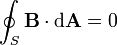
Physics equations/Sheet/All chapters
< Physics equations < Sheet00-Mathematics_for_this_course
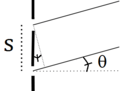
Measured in radians,  defines angle (in radians), where s is arclength and r is radius. The circumference of a circle is
  and the circle's area is
  is its area. The surface area of a sphere is
  and sphere's volume is
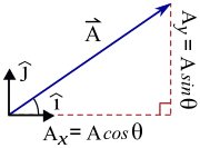
A vector can be expressed as, 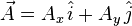 , where
  , and
, and  are the x and y components. Alternative notation for the unit vectors
  include
  and
and  . An important vector is the displacement from the origin, with components are typically written without subscripts:
  . The magnitude (or absolute value or norm) of a vector is is
  , where the angle (or phase),
  , obeys
  , or (almost) equivalently,
  . As with any function/inverse function pair, the tangent and arctangent are related by
  where
where  . The arctangent is not a true function because it is multivalued, with
  .
.
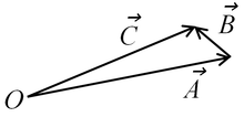
The geometric interpretations of  and
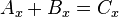
and  are shown in the figure. Vector addition and subtraction can also be defined through the components:
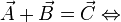
 AND
AND 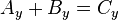 01-Introduction
|
- 1 kilometer = .621 miles and 1 MPH = 1 mi/hr ≈ .447 m/s
- Typically air density is 1.2kg/m3, with pressure 105Pa. The density of water is 1000kg/m3.
- Earth's mean radius ≈ 6371km, mass ≈ 6×1024
kg, and gravitational acceleration = g ≈ 9.8m/s2 - Universal gravitational constant = G ≈ 6.67×10⁻¹¹
m3·kg−1·s−2 - Speed of sound ≈ 340m/s and the speed of light = c ≈ 3×10⁸m/s
- One light-year ≈ 9.5×10¹⁵m ≈ 63240AU (Astronomical unit)
- The electron has charge, e ≈ 1.6 × 10⁻¹⁹C and mass ≈ 9.11 × 10⁻³¹kg. 1eV = 1.602 × 10⁻¹⁹J is a unit of energy, defined as the work associated with moving one electron through a potential difference of one volt.
- 1 amu = 1 u ≈ 1.66 × 10⁻²⁷ kg is the approximate mass of a proton or neutron.
- Boltzmann's constant = kB≈ 1.38 × 10⁻²³ J K−1 , and the gas constant is R = NAkB≈8.314 J K−1 mol−1, where NA≈ 6.02 × 10²³ is the Avogadro number.
 ≈ 8.987× 10⁹ N·m²·C−2 is a fundamental constant of electricity; also
  ≈ 8.854 × 10⁻¹² F·m−1 is the vacuum permittivity.
 = 4π × 10−7 NA ≈ 1.257 × 10⁻⁶ N A (magnetic permeability) is the fundamental constant of magnetism:
  .
. = h/(2π) ≈ 1.054×10⁻³⁴ J·s the reduced Planck constant, and
 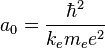 ≈ .526 × 10−10 m is the Bohr radius.
Two dimensional kinematics
Difference is denoted by  ,
,  , or the Delta.
  or
or  . Average, or mean, is denoted by
  , where
  is number and
  are probabilities. The average velocity is
  , and the average acceleration is
  , where
  denotes position. In CALCULUS, instantaneous values are denoted by v(t)=dx/dt and a=dv/dt=d2x/dt2.
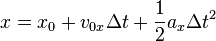
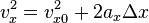
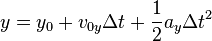
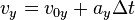
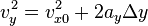
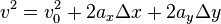
The equations of motion for uniform acceleration are:  , and,
  . Also,
  , and,
 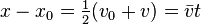 . Note that
 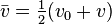 only if the acceleration is uniform.
03-Two-Dimensional_Kinematics
only if the acceleration is uniform.
03-Two-Dimensional_Kinematics
 |
 |
 |
 |
 |
 |
 ...in advanced notation this becomes
 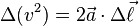 .
.
In free fall we often set, ax=0 and ay= -g. If angle is measured with respect to the x axis:


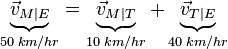
The figure shows a Man moving relative to Train with velocity,  , where the velocity of the train relative to Earth is,
  is the velocity of the Train relative to Earth. The velocity of the Man relative to Earth is,
 If the speeds are relativistic, define u=v/c where c is the speed of light, and this formula must be modified to:
 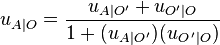 04-Dynamics:_Force_and_Newton's_Laws
Newton's laws of motion, can be expressed with two equations, 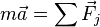 and
and  . The second represents the fact that the force that the i-th object exerts one object exerts on the j-th object is equal and opposite the force that the j-th exerts on the i-th object. Three non-fundamental fores are:
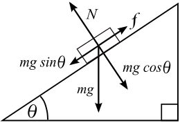
- The normal force,
 , is a contact forces that is perpendicular to the surface,
 - The force of friction,
 , is a contact force that is parallel to the surface.
 - Tension,
 , is often associated with ropes and strings. If the rope has sufficiently low weight and of all external forces act at the two ends, then this tension is distributed uniformly along the rope.
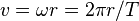
 - The fourth force is fundamental: Weight equals
 , and is the force of gravity acting on an object of mass,
  . At Earth's surface,
  .
.
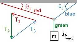
The x and y components of the three forces of tension on the small grey circle where the three "massless" ropes meet are:
 ,
, 
 ,
, 
 ,
, 
05-Friction,_Drag,_and_Elasticity
 is an approximation for the force friction when an object is sliding on a surface, where μk ("mew-sub-k") is the kinetic coefficient of friction, and N is the normal force.
 approximates the maximum possible friction (called static friction) that can occur before the object begins to slide. Usually μs > μk.
Also, air drag often depends on speed, an effect this model fails to capture. 06-Uniform_Circular_Motion_and_Gravitation
-
 relates the radian, degree, and revolution.
 is the number of revolutions per second, called frequency.
 is the number of seconds per revolution, called period. Obviously
  .
.
 is called angular frequency (ω is called omega, and θ is measured in radians). Obviously
-
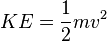
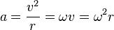 is the acceleration of uniform circular motion, where v is speed, and r is radius.
 -
 , where T is period.
-
 is the force of gravity between two objects, where the universal constant of gravity is G ≈ 6.674 × 10⁻¹¹ m3·kg−1·s−2.
07-Work_and_Energy
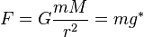
 is kinetic energy, where m is mass and v is speed..
 is gravitational potential energy,where y is height, and
  is the gravitational acceleration at Earth's surface.
 is the potential energy stored in a spring with spring constant
  .
. relates the final energy to the initial energy. If energy is lost to heat or other nonconservative force, then Q>0.
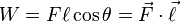 (measured in Joules) is the work done by a force
  as it moves an object a distance
  . The angle between the force and the displacement is θ.
 describes the work if the force is not uniform. The steps,
  , taken by the particle are assumed small enough that the force is approximately uniform over the small step. If force and displacement are parallel, then the work becomes the area under a curve of F(x) versus x.
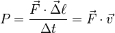 is the power (measured in Watts) is the rate at which work is done. (v is velocity.)
08-Linear_Momentum_and_Collisions
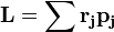
 is momentum, where m is mass and
  is velocity. The net momemtum is conserved if all forces between a system of particles are internal (i.e., come equal and opposite pairs):
 .
.  is the impulse, or change in momentum associated with a brief force acting over a time interval
  . (Strictly speaking,
  is a time-averaged force defined by integrating over the time interval.)
09-Statics_and_Torque
-
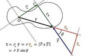
 is the torque caused by a force, F, exerted at a distance ,r, from the axis. The angle between r and F is θ.
The SI units for torque is the newton metre (N·m). It would be inadvisable to call this a Joule, even though a Joule is also a (N·m). The symbol for torque is typically τ, the Greek letter tau. When it is called moment, it is commonly denoted M.[1] The lever arm is defined as either r, or r⊥. Labeling r as the lever arm allows moment arm to be reserved for r⊥. 10-Rotational_Motion_and_Angular Momentum
| Linear motion | Angular motion |
|---|---|
 |
 |
 |
 |
 |
 |
 |
 |
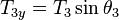
The following table refers to rotation of a rigid body about a fixed axis:  is arclength,
  is the distance from the axis to any point, and
  is the tangential acceleration, which is the component of the acceleration that is parallel to the motion. In contrast, the centripetal acceleration,
  , is perpendicular to the motion. The component of the force parallel to the motion, or equivalently, perpendicular, to the line connecting the point of application to the axis is
  . The sum is over
  particles or points of application.
| Linear motion | Rotational motion | Defining equation |
|---|---|---|
Displacement =  |
Angular displacement = |
 |
Velocity =  |
Angular velocity =  |
 |
Acceleration =  |
Angular acceleration =  |
 |
Mass =  |
Moment of Inertia =  |
 |
Force =  |
Torque =  |
 |
Momentum=  |
Angular momentum=  |
 |
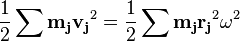
Kinetic energy =  |
Kinetic energy =  |
 |
| Description[3] | Figure | Moment(s) of inertia |
|---|---|---|
| Rod of length L and mass m (Axis of rotation at the end of the rod) |
 |
 |
| Solid cylinder of radius r, height h and mass m |  |
 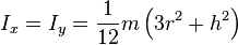 |
| Sphere (hollow) of radius r and mass m |  |
 |
| Ball (solid) of radius r and mass m | 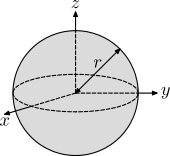 |
 |
11-Fluid_statics

Pressure versus Depth: A fluid's pressure is F/A where F is force and A is a (flat) area. The pressure at depth,  below the surface is the weight (per area) of the fluid above that point. As shown in the figure, this implies:
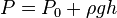
where  is the pressure at the top surface, is the depth, and
  is the mass density of the fluid. In many cases, only the difference between two pressures appears in the final answer to a question, and in such cases it is permissible to set the pressure at the top surface of the fluid equal to zero. In many applications, it is possible to artificially set equal to zero, for example at atmospheric pressure. The resulting pressure is called the gauge pressure, for
 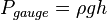 below the surface of a body of water.
Buoyancy and Archimedes' principle Pascal's principle does not hold if two fluids are separated by a seal that prohibits fluid flow (as in the case of the piston of an internal combustion engine). Suppose the upper and lower fluids shown in the figure are not sealed, so that a fluid of mass density  comes to equilibrium above and below an object. Let the object have a mass density of
  and a volume of
  , as shown in the figure. The net (bottom minus top) force on the object due to the fluid is called the buoyant force:
 ,
,
and is directed upward. The volume in this formula, AΔh, is called the volume of the displaced fluid, since placing the volume into a fluid at that location requires the removal of that amount of fluid. Archimedes principle states:
- A body wholly or partially submerged in a fluid is buoyed up by a force equal to the weight of the displaced fluid.
Note that if  , the buoyant force exactly cancels the force of gravity. A fluid element within a stationary fluid will remain stationary. But if the two densities are not equal, a third force (in addition to weight and the buoyant force) is required to hold the object at that depth. If an object is floating or partially submerged, the volume of the displaced fluid equals the volume of that portion of the object which is below the waterline.
12-Fluid_dynamics
, the buoyant force exactly cancels the force of gravity. A fluid element within a stationary fluid will remain stationary. But if the two densities are not equal, a third force (in addition to weight and the buoyant force) is required to hold the object at that depth. If an object is floating or partially submerged, the volume of the displaced fluid equals the volume of that portion of the object which is below the waterline.
12-Fluid_dynamics
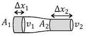
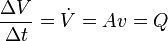 the volume flow for incompressible fluid flow if viscosity and turbulence are both neglected. The average velocity is
  and
and  is the cross sectional area of the pipe. As shown in the figure,
  because
  is constant along the developed flow. To see this, note that the volume of pipe is
  along a distance
  . And,
  is the volume of fluid that passes a given point in the pipe during a time .
 is Bernoulli's equation, where
  is pressure, is density, and
  is height. This holds for inviscid flow.
13-Temperature,_Kinetic Theory,_and_Gas_Laws
-
 converts from Celsius to Kelvins, and
 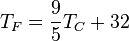 converts from Celsius to Fahrenheit.
 -
 is the ideal gas law, where P is pressure, V is volume, n is the number of moles and N is the number of atoms or molecules. Temperature must be measured on an absolute scale (e.g. Kelvins).
 - NAkB=R where NA= 6.02 × 10²³ is the Avogadro number. Boltzmann's constant can also be written in eV and Kelvins: kB ≈8.6 × 10⁻⁵ eV/deg.
-
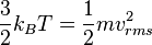 is the average translational kinetic energy per "atom" of a 3-dimensional ideal gas.
 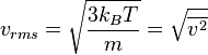 is the root-mean-square speed of atoms in an ideal gas.
-
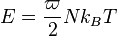 is the total energy of an ideal gas, where
14-Heat_and_Heat_Transfer
Here it is convenient to define heat as energy that passes between two objects of different temperature  The SI unit is the Joule. The rate of heat trasfer,
  or
or  is "power": 1 Watt = 1 W = 1J/s
-
 is the heat required to change the temperature of a substance of mass, m. The change in temperature is ΔT. The specific heat, cS, depends on the substance (and to some extent, its temperature and other factors such as pressure). Heat is the transfer of energy, usually from a hotter object to a colder one. The units of specfic heat are energy/mass/degree, or J/(kg-degree).
 -
 is the heat required to change the phase of a a mass, m, of a substance (with no change in temperature). The latent heat, L, depends not only on the substance, but on the nature of the phase change for any given substance. LF is called the latent heat of fusion, and refers to the melting or freezing of the substance. LV is called the latent heat of vaporization, and refers to evaporation or condensation of a substance.
 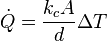 is rate of heat transfer for a material of area, A. The difference in temperature between two sides separated by a distance, d, is
  . The thermal conductivity, kc, is a property of the substance used to insulate, or subdue, the flow of heat.
-
 is the power radiated by a surface of area, A, at a temperature, T, measured on an absolute scale such as Kelvins. The emissivity,
  , is 1 for a black body, and 0 for a perfectly reflecting surface. The Stefan-Boltzmann constant is
  .
.
15-Thermodynamics
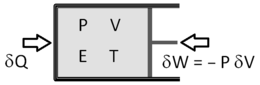
- Pressure (P), Energy (E), Volume (V), and Temperature (T) are state variables (state functionscalled state functions). The number of particles (N) can also be viewed as a state variable.
- Work (W), Heat (Q) are not state variables.
-
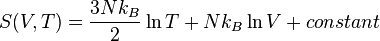 , is the entropy of an ideal , monatomic gas. The constant is arbitrary only in classical (non-quantum) thermodynamics. Since it is a function of state variables, entropy is also a state function.
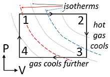
A point on a PV diagram define's the system's pressure (P) and volume (V). Energy (E) and pressure (P) can be deduced from equations of state: E=E(V,P) and T=T(V,P). If the piston moves, or if heat is added or taken from the substance, energy (in the form of work and/or heat) is added or subtracted. If the path returns to its original point on the PV-diagram (e.g., 12341 along the rectantular path shown), and if the process is quasistatic, all state variables (P, V, E, T) return to their original values, and the final system is indistinguishable from its original state.
The net work done per cycle is area enclosed by the loop. This work equals the net heat flow into the system,  (valid only for closed loops).
Remember: Area "under" is the work associated with a path; Area "inside" is the total work per cycle.
-
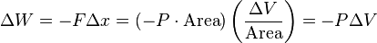 is the work done on a system of pressure P by a piston of voulume V. If ΔV>0 the substance is expanding as it exerts an outward force, so that ΔW<0 and the substance is doing work on the universe; ΔW>0 whenever the universe is doing work on the system.
 -
 is the amount of heat (energy) that flows into a system. It is positive if the system is placed in a heat bath of higher temperature. If this process is reversible, then the heat bath is at an infinitesimally higher temperature and a finite ΔQ takes an infinite amount of time.
 -
 is the change in energy (First Law of Thermodynamics).
CALCULUS: 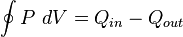 .
.
- In an isothermal expansion (contraction), temperature, T, is constant. Hence P=nRT/V and substitution yields,

16-Oscillatory_Motion_and_Waves
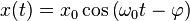
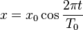 describes oscillatory motion with period
  (here we use the zero-subscript to denote constants that do not vary with time).
-
 . For example,
  .
. 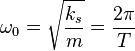 for a mass-spring system with mass, m, and spring constant, ks.
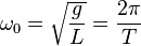 for a low amplitude pendulum of length, L, in a gravitational field, g.
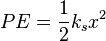 is the potential energy of a mass spring system.
Let  describe position:
-
 , where
  is maximum velocity.
  , where
  , is maximum acceleration.
-
 , relates maximum force to maximum acceleration.
  is the total energy.
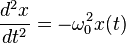
- CALCULUS: x(t) obeys the linear homogeneous differential equation (ODE),
 relates the frequency, f, wavelength, λ,and the the phase speed, vp of the wave (also written as vw) This phase speed is the speed of individual crests, which for sound and light waves also equals the speed at which a wave packet travels.
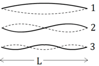
  describes the n-th normal mode vibrating wave on a string that is fixed at both ends (i.e. has a node at both ends). The mode number, n = 1, 2, 3,..., as shown in the figure.
- Beat frequency: The frequency of beats heard if two closely space frequencies,
 and
and  , are played is
  .
. - Musical acoustics: Frequency ratios of 2/1, 3/2, 4/3, 5/3, 5/4, 6/5, 8/5 are called the (just) "octave", "fifth", "fourth", "major-sixth", "major-third", "minor-third", and "minor-sixth", respectively.
17-Physics_of_Hearing
 is the the approximate speed near Earth's surface, where the temperature, T, is measured in Kelvins. A theoretical calculation is
  where
where  for a semi-classical gas with
  degrees of freedom. For a diatomic gas such as Nitrogen, γ = 1.4.
 is the speed of a wave in a stretched string if is the tension and
  is the linear mass density (kilograms per meter).
18-Electric_charge_and_field
 is Coulomb's law for the force between two charged particles separated by a distance r: ke≈8.987×10⁹N·m²·C−2, and ε0≈8.854×10⁻¹² F·m−1.
  is the electric force on a "test charge", q, where
  is the magnitude of the electric field situated a distance r from a charge, Q.
Consider a collection of particles of charge  , located at points
  (called source points), the electric field at
  (called the field point) is:
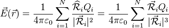 is the electric field at the field point, , due to point charges at the source points, , and
 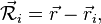 points from source points to the field point.
CALCULUS supplement:
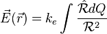 is the electric field due to distributed charge, where
  , and
, and  denote linear, surface, and volume density (or charge density), respectively.
Cartesian coordinates (x, y, z). Volume element: 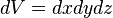 . Line element:
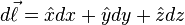 . Three basic area elements:
 , or,
, or, , or,
, or, .
.
Cylindrical coordinates (ρ, φ, z): Volume element: 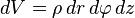 . Line element:
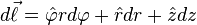 . Basic area elements:
 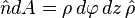 (side), and,
  (top end).
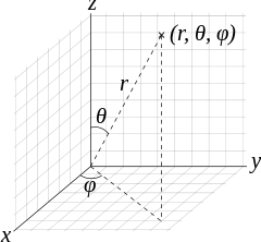
Spherical coordinates (r, θ, φ): Volume element:  (if symmetry holds). Line element:
 . Basic area element of a sphere:
  , where dΩ is a solid angle.
19-Electric_Potential_and_Electric_Field
, where dΩ is a solid angle.
19-Electric_Potential_and_Electric_Field
 is the potential energy of a particle of charge, q, in the presence of an electric potential V.
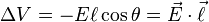 (measured in Volts) is the variation in electric potential as one moves through an electric field
  . The angle between the field and the displacement is θ. The electric potential, V, decreases as one moves parallel to the electric field.
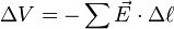 describes the electric potential if the field is not uniform.
 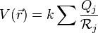 due to a set of charges
  at
at  where
where  .
.
-
 is the (equal and opposite) charge on the two terminals of a capacitor of capicitance, C, that has a voltage drop, V, across the two terminals.
  is the capacitance of a parallel plate capacitor with surface area, A, and plate separation, d. This formula is valid only in the limit that d2/A vanishes. If a dielectric is between the plates, then ε>ε0≈ 8.85 × 10⁻¹² due to shielding of the applied electric field by dielectric polarization effects.
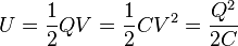 is the energy stored in a capacitor.
 is the energy density (energy per unit volume, or Joules per cubic meter) of an electric field.
CALCULUS supplement
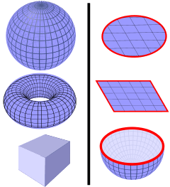
To the left are closed surfaces. To the right are open surfaces, Ω, that possess closed boundaries, ∂Ω.
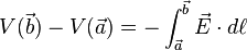
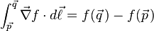 is the gradient theorem.
 is
is 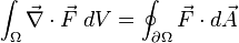 is the divergence theorem
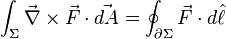
Here, Ω is a (3-dimensional) volume and ∂Ω is the boundary of the volume, which is a (two-dimensional) surface. Also a surface is Σ, which, if open, has the boundary ∂Σ, which is a (one-dimensional) curve.
 in the limit that the Riemann sum becomes an integral.
  where
where 
 is the del operator.
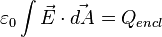 is Gauss's law for the surface integral of the electric field over any closed surface, and
  is the total charge inside that surface.
  is a useful variant if the medium is dielectric. D=εE is the electric displacement field. The permittivity, ε = (1+χ)ε0, where ε0≈ 8.85 × 10⁻¹², and the electric susceptibility, χ, represents the degree to which the medium can be polarized by an electric field. The free charge, Qfree, represents all charges except those represented by the susceptibility, χ.
20-Electric_Current,_Resistance,_and_Ohm's_Law
 defines the electric current as the rate at which charge flows past a given point on a wire. The direction of the current matches the flow of positive charge (which is opposite the flow of electrons if electrons are the carriers.)
 is Ohm's Law relating current, I, and resistance, R, to the difference in voltage, V, between the terminals. The resistance, R, is positive in virtually all cases, and if R > 0, the current flows from larger to smaller voltage. Any device or substance that obeys this linear relation between I and V is called ohmic.
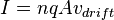 relates the density (n), the charge(q), and the average drift velocity (vdrift) of the carriers. The area (A) is measured by imagining a cut across the wire oriented such that the drift velocity is perpendicular to the surface of the (imaginary) cut.
  expresses the resistance of a sample of ohmic material with a length (L) and area (A). The 'resistivity', ρ ("row"), is an intensive property of matter.
- Power is energy/time, measured in joules/second or J/s. Often called P (never p). It is measured in watts (W)
- Current is charge/time, measured in coulombs/second or C/s. Often called I or i. It is measured in amps or ampheres (A)
- Electric potential (or voltage) is energy/charge, measured in joules/coulomb or J/C. Often called V (sometimes E, emf,
 ). It is measured in volts (V)
 - Resistance is voltage/current , measured in volts/amp or V/A. Often called R (sometimes r, Z) It is measured in Ohms (Ω).
 is the power dissipated as current flows through a resistor
21-Circuits,_Bioelectricity,_and_DC_Instruments
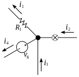 The current entering any junction is equal to the current leaving that junction. i2 + i3 = i1 + i4 |
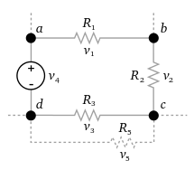 The sum of all the voltages around the loop is equal to zero. v1 + v2 + v3 - v4 = 0 |
 Resistors in parallel |
Resistors in series |
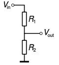
 and
and  are Kirchoff's Laws[4]
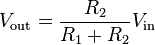 for the voltage divider shown.
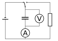
- Simple RC circuit[5] The figure to the right depicts a capacitor being charged by an ideal voltage source. If, at t=0, the switch is thrown to the other side, the capacitor will discharge, with the voltage, V , undergoing exponential decay:
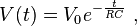
where V0 is the capacitor voltage at time t = 0 (when the switch was closed). The time required for the voltage to fall to  is called the RC time constant and is given by

22-Magnetism
-
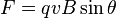 is the force on a particle with charge q moving at velocity v with in the presence of a magnetic field B. The angle between velocity and magnetic field is θ and the force is perpeduclar to both velocity and magnetic field by the right hand rule.
 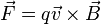 expresses this result as a cross product.
-
 is the force a straight wire segment of length
  carrying a current, I.
 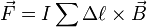 expresses thus sum over many segments to model a wire.
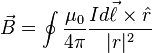
 - CALCULUS: In the limit that
 we have the integral,
 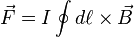 .
.
- Defining magnetic force and field without calculus:
-
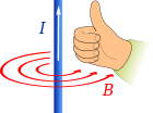
 is the magnetic field at a distance r from an infinitely long wire carrying a current, where μ0 = 4π × 10−7 N A. This field points azimuthally around the wire in a direction defined by the right hand rule. Application of the force law on a current element, we have
 -
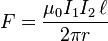 is the force between two long wires of length separated by a short distance
  . The currents are I1 and I2, with the force being attractive if the currents are flowing in the same direction.
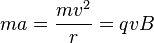
Cyclotron motion: For a particle moving perpendicular to B, we have cyclotron motion. Recall that for uniform circular motion, the acceleration is a=v2/r, where r is the radius. Since sin θ =1, Newton's second law of motion (F=ma) yields,
Since, sin θ =0, for motion parallel to a magnetic field, particles in a uniform magnetic field move in spirals at a radius which is determined by the perpendicular component of the velocity:

Hall effect: The Hall effect occurs when the magnetic field, velocity, and electric field are mutually perpendicular. In this case, the electric and magnetic forces are aligned, and can cancel if qE=qvB (since sinθ = 1). Since both terms are porportional to charge, q, the appropriate ratio of electric to magnetic field for null net force depends only on velocity:
 ,
,
where we have used the fact that voltage (i.e. emf or potential) is related to the electric field and a displacement parallel to that field: ΔV = -E Δs cosθ
CALCULUS supplement:
-
 and the volume integral
 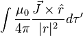 , where
  is current density.
 -
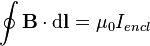 is Ampere's law relating a closed integral involving magnetic field to the total current enclosed by that path.
23-Electromagnetic_Induction,_AC_Circuits,_and_Electrical_Technologies
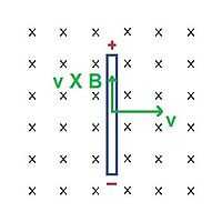
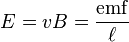
 is a consequence of the magnetic force law as seen in the reference frame of a moving charged object, where E is the electric field perceived by an observer moving at velocity v in the presence of a magnetic vield, B. Also written as, E = vBsinθ, this can be used to derive Faraday's law of induction. (Here, θ is the angle between the velocity and the magnetic field.)
 is the magnetic flux, where θ is the angle between the magnetic field and the normal to a surface of area, A.
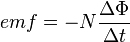 is Faraday's law where t is time and N is the number of turns. The minus sign reminds us that the emf, or electromotive force, acts as a "voltage" that opposes the change in the magnetic field or flux.
24-Electromagnetic_Waves
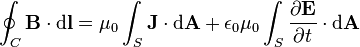
-
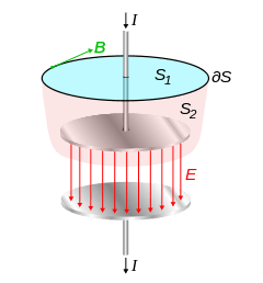
 is called the displacement current because it replaces the current density when using Ampère's circuital law to calculate the line integral of the magnetic field around a closed loop.
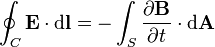
Maxwell's equations hold for all volumes and closed surfaces. In vacuum, electromagnetic waves travel at the speed,  .
.
 |
 |
 |
 |
25-Geometric_Optics
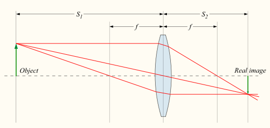
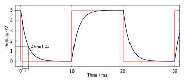
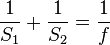 relates the focal length f of the lens, the image distance S1, and the object distance S2. The figure depicts the situation for which (S1, S2, f) are all positive: (1)The lens is converging (convex); (2) The real image is to the right of the lens; and (3) the object is to the left of the lens. If the lens is diverging (concave), then f < 0. If the image is to the left of the lens (virtual image), then S2 < 0 .
27-Wave_Optics
-
 where
where  describes the constructive interference associated with two slits in the Fraunhoffer (far field) approximation.
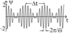
 where
where  is the high frequency carrier and
 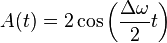 is the slowly varying envelope. Here,
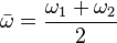 and
and  . Consequently, the beat frequency heard when two tones of frequency and is
  .
.
 models the addition of two waves of equal amplitude but different path length,
  .
.
- ↑ https://en.wikipedia.org/w/index.php?title=Torque&oldid=582917749
- ↑ "Linear Motion vs Rotational motion".
- ↑ https://en.wikipedia.org/w/index.php?title=List_of_moments_of_inertia&oldid=582953751
- ↑ https //en.wikipedia.org/w/index.php?title=Kirchhoff%27s_circuit_laws&oldid=579357795
- ↑ From https://en.wikipedia.org/w/index.php?title=RC_circuit&oldid=598786790