Physics Formulae/Electric Circuits Formulae
< Physics FormulaeLead Article: Tables of Physics Formulae
This article is a summary of the laws, principles, defining quantities, and useful formulae in the analysis of Electric Circuits, Electronics.
DC Quantities
| Quantity (Common Name/s) | (Common) Symbol/s | Defining Equation | SI Units | Dimension |
|---|---|---|---|---|
| Electrical Resistance |  |
 |
Ω = V A-1 = J s C-2 | [M][L]2 [T]-3 [I]-2 |
| Resistivity, Scalar |  |
 |
Ω m | [M]2 [L]2 [T]-3 [I]-2 |
| Resistivity Temperature Coefficient,
Linear Temperature Dependance |
 |
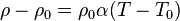 |
K-1 | [Θ]-1 |
| Terminal Voltage for
Power Supply |
 |
V = J C-1 | [M] [L]2 [T]-3 [I]-1 | |
| Load Voltage for Circuit |  |
V = J C-1 | [M] [L]2 [T]-3 [I]-1 | |
| Internal Resistance of
Power Supply |
 |
 |
Ω = V A-1 = J s C-2 | [M][L]2 [T]-3 [I]-2 |
| Load Resistance of
Circuit |
 |
 |
Ω = V A-1 = J s C-2 | [M][L]2 [T]-3 [I]-2 |
| Electromotive Force (emf), Voltage across
entire circuit including power supply, external components and conductors |
 |
 |
V = J C-1 | [M] [L]2 [T]-3 [I]-1 |
| Electrical Conductance |  |
 |
S = Ω-1 | [T]3 [I]2 [M]-1 [L]-2 |
| Electrical Conductivity, Scalar |  |
 |
Ω-1 m-1 | [I]2 [T]3 [M]-2 [L]-2 |
| Electrical Conductivity, Tensor |  |
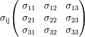 |
Ω-1 m-1 | [I]2 [T]3 [M]-2 [L]-2 |
| Electrical Power |  |
 |
W = J s-1 | [M] [L]2 [T]-3 |
| emf Power | |
 |
W = J s-1 | [M] [L]2 [T]-3 |
| Resistor Power Dissipation | |
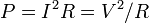 |
W = J s-1 | [M] [L]2 [T]-3 |
| Resistors in Series | 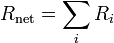 |
| Resistors in Parallel | 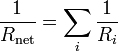 |
| Ohm's Law | Scalar form
Vector Form
Tensor Form, general applies to all points in a conductor
|
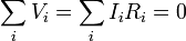
| Kirchoff's Laws | emf loop rule around any closed circuit
Current law at junctions
|


AC Quantitites
| Quantity (Common Name/s) | Common Name/s | Quantity (Common Name/s) | Quantity (Common Name/s) | Quantity (Common Name/s) |
|---|---|---|---|---|
| Resistive Load Voltage |  |
 |
V = J C-1 | [M] [L]2 [T]-3 [I]-1 |
| Capacitive Load Voltage |  |
 |
V = J C-1 | [M] [L]2 [T]-3 [I]-1 |
| Inductive Load Voltage |  |
 |
V = J C-1 | [M] [L]2 [T]-3 [I]-1 |
| Capacitive Reactance |  |
 |
Ω-1 m-1 | [I]2 [T]3 [M]-2 [L]-2 |
| Inductive Reactance |  |
 |
Ω-1 m-1 | [I]2 [T]3 [M]-2 [L]-2 |
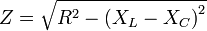
| AC Impedance |  |

|
Ω-1 m-1 | [I]2 [T]3 [M]-2 [L]-2 |
| Phase Constant |  |
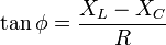 |
dimensionless | dimensionless |
| AC Circuit Resonant
Pulsatance |
 |
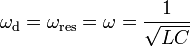 |
s-1 | [T]-1 |
| AC Peak Current |  |
 |
A | [I] |
| AC Root Mean
Square Current |
 |
![I_\mathrm{rms} = \sqrt{\frac{1}{T} \int_{0}^{T} \left [ I \left ( t \right ) \right ]^2 \mathrm{d} t} \,\!](../I/m/3dc612366a1a6a3ae60a4d72d53c0767.png) |
A | [I] |
| AC Peak Voltage |  |
 |
V = J C-1 | [M] [L]2 [T]-3 [I]-1 |
| AC Root Mean
Square Voltage |
 |
![V_\mathrm{rms} = \sqrt{\frac{1}{T} \int_{0}^{T} \left [ V \left ( t \right ) \right ]^2 \mathrm{d} t} \,\!](../I/m/d0db1de2c13f2b62e6544e8171212c03.png) |
V = J C-1 | [M] [L]2 [T]-3 [I]-1 |
| AC emf, Root Mean Square |  |
 |
V = J C-1 | [M] [L]2 [T]-3 [I]-1 |
| AC Average Power |  |
 |
W = J s-1 | [M] [L]2 [T]-3 |
| Capacitive Time Constant |  |
 |
s | [T] |
| Inductive Time Constant |  |
 |
s | [T] |
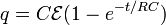
| RC Circuits | RC Circuit Equation
RC Circuit Capacitor Charging
|
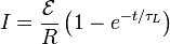
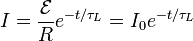
| RL Circuits | RL Circuit Equation
RL Circuit Current Rise
RL Circuit, Current Fall
|
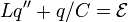
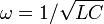
| LC Circuit | LC Circuit Equation
LC Circuit Resonance
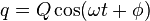
LC Circuit Charge
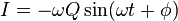
LC Circuit Current
LC Circuit electrical potential energy
LC circuit magnetic potential energy
|
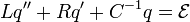
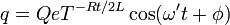
| RLC Circuits | RLC Circuit Equation
RLC Circuit Charge
|


This article is issued from Wikiversity - version of the Friday, July 17, 2015. The text is available under the Creative Commons Attribution/Share Alike but additional terms may apply for the media files.