Operational amplifier
The operational amplifier, often referred to informally as an op amp, is a circuit that provides extremely high-gain amplification of the difference in voltage between two inputs. One input is known as the inverting input and the other is known as the non-inverting input. There is only a single output. The input impedance of the inverting and non-inverting inputs is extremely high. The output impedance of the op amp is very low. Modern op amps are integrated circuits.
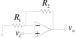
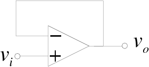
The standard symbol for an op amp is shown below:
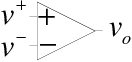
Not shown in this symbol are connections for the power supplies. Omitting them from schematic drawings is customary, although in practice they must be connected. Op amps are available with bipolar or unipolar power supplies.
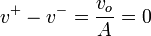
Noting that  and solving the second of these equations for
  gives
gives

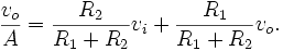
Now we can substitute this into the first of our two equations:
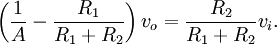
Subtracting  from both sides and factoring out
  on the left hand side yields
Dividing boths sides by 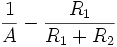 and by
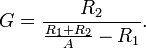
  yields the gain
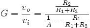
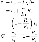
This can be rewritten more simply if both numerator and denominator are multiplied by  :
:
Now if  is very large, the first term in the denominator can be neglected and the gain is
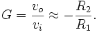
This shows that the amplification constant of the op amp vanishes from the overall expression for the gain because it is very large. The gain of the circuit is instead determined solely by the external components. This means that the high variability of in manufacture does not affect the behaviour of the circuit in which the op amp is embedded. As long as is sufficiently large, the approximation is reasonable.
The configuration we have analyzed here is that of an inverting amplifier. It is inverted because of the negative sign. The magnitude of the gain is determined by the ratio of  and can be either greater than or less than one.
Ideal Op Amps
Analysis of circuits with op amps in them can be simplified by assuming two idealizations of an op amp's behaviour:
-

- The currents entering the inverting and non-inverting terminals of the op amp are zero.
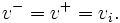
A consequence of the first of these idealizations is that the voltages at both input terminals must be equal:
In the circuit analyzed above, this means that  because
  is grounded.
Of course, in reality and cannot be precisely equal, for if they were, the output of the amplifier would be zero. However, because is very large, the difference is very small and we assume it can be neglected.
Using the idealized behaviour lets us calculate the current flowing through  from left to right very simply as

The second of the two idealizations means that all this current flows through  . None of it can flow into the inverting terminal of the op amp. Consequently,
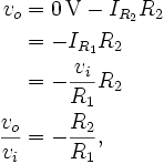
as before. We achieve the same result, but using the idealized model of an op amp permits us to do so with substantially less analysis. In general, assuming that an op amp behaves in this ideal manner makes it easy to get a rough idea of how a circuit will behave.
Later on we will see that the dependence of on frequency will require us to investigate the behaviour of our circuit more carefully when the inputs contain higher frequencies.
Non-inverting Amplifier
Consider next this circuit:
Using the idealized op amp assumptions, we see that
This means that current flowing from right to left through is

and all of this current must also flow from right to left through since the op amp takes in no current at its input terminals. So we can find
In this configuration the gain is positive and at least as great as one. This configuration provides a non-inverting amplifier.
Voltage Follower (Current Buffer)
The op amp in this configuration:
is identical to the non-inverting amplifier configuration if we pick  and
and  . The output, therefore, is

Because the ideal op amp draws no current from the source and because it has very low output impedance, this circuit provides a replica of the input without loading the circuit that provides the input voltage. Many sensors, such as some microphones, have a high output impedance. Drawing current from them would result in a reduction of the voltage sensed by the amplifier. This circuit prevents that, leading to the alternate name current buffer for this circuit.
Output Impedance
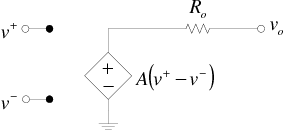
Up to this point we have tacitly treated the output impedance of an op amp as zero. The output impedance of a typical op amp, such as the LM741, is around 75 Ω. A more suitable model of an op amp treats it as a voltage-controlled voltage source with an output resistance  . Such a model looks like this:
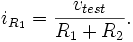
To calculate the output impedance of a circuit such as the inverting amplifier configuration, suppress the input voltage, apply a test voltage to the output, and calculate the output current. Taking the ratio of test voltage divided by output current gives the output resistance. The circuit arrangement is shown in the figure below.
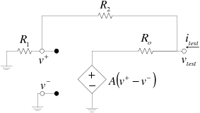
Since negligible current enters the op amp at its inverting terminal, we can calculate the current flowing from right to left through as
We can also calculate the current flowing from right to left through as
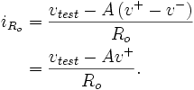
Adding these two currents together gives
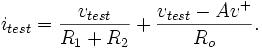
The quantity is given by  , so
, so
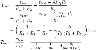
For sufficiently large values of the third term in the denominator dominates the first two, forcing  to become much smaller than , the output resistance of the op amp itself.
Notice that the same analysis applies to the non-inverting configuration because, when the input voltages are suppressed, it is indistinguishable from the inverting amplifier just analyzed.
This analysis shows that one of the great benefits of using op amps with large gain is that they make it possible to build circuits with very small output impedance. This means that when connected as a source to other circuit elements, there is a negligible signal loss at the next stage's input.
Practical Usage
Comparator
The amplification of the operational amplifier depends purely upon the ratio of a feedback resistor to the input resistor. And now, let us assume that the feedback resistor is missing, and the input is connected directly to the op amp IC without and input resistors.
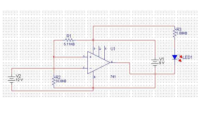
If the input resistor is missing, the gain loop is open. In another word we can say that the Feedback Resistance is infinitely high, and the gain of the operational amplifier is infinitely high. However, what does determine the sign (+/-) of the gain. This is the difference between negative and positive inputs.
- In non-inverting amplifier circuit the inverting input is grounded (through resistors), and the input goes to positive.
- In the inverting amplifier circuit, the non-inverting input is grounded, and the input goes to the inverting input.
- In both cases the voltage on the non-in-use input is close to ZERO. Therefore the incoming signal is absolute.
In comparator, a reference voltage is supplied to the positive input, and the negative input measures the input voltage. The reference voltage is obtained by a simple voltage divider.
So, if the input voltage will be less then reference voltage, the output will bi “infinitely negative” And if the input voltage will be higher then reference voltage, the output voltage will be “infinitely positive”.
However, as in any amplifier, the highest value of the output is dictated by the power voltage. So the word “infinite” should be changed by “maximal” or “as high as power voltage”.
SO
  If (input_voltage > reference voltage)
      Output Voltage = NEGATIVE
  If (input_voltage < reference voltage)
      Output voltage = POSITIVE.
For the further analysis, let us consider the output of the op amp just as a voltage source. Along with a power source circuit, and the LED (Light Emitting Diode) they form a circuit which highs up in case when a current flows through the circuit.
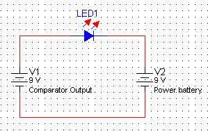 When the comparator output is high, the output circuit is similar to that one, on the LEFT drawing.
“batteries” are coupled so, that their net voltage is 0, and if we assume that the voltage in the circuit is 0, the LED will NOT light.
When the comparator output is high, the output circuit is similar to that one, on the LEFT drawing.
“batteries” are coupled so, that their net voltage is 0, and if we assume that the voltage in the circuit is 0, the LED will NOT light.
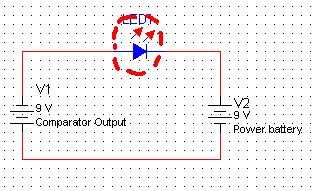 When the comparator input is low, we can assume the circuit on the RIGHT figure. IT has voltage of 18 Volts, so the LED will LIGHT UP.
Conclusion
Led lights up when the voltage on the negative input is more then the voltage on the point between two resistors. R1 and R2. In our case it was…6.6.V When we switched the resistors it became…. 2.5 V
Pin Configuration
For a standard 8-pin, 741 type Operational Amplifier (IC), the following pin configuration has to be implemented for its operation to be successful:
| Pin | Useage |
|---|---|
| 1 | Offset Null |
| 2 | Inverted Input |
| 3 | Non-Inverted Input |
| 4 | -V Supply |
| 5 | No use |
| 6 | Output |
| 7 | +V Supply |
| 8 | No use |
Historical notice
This amplifier is called operational because of its original intent to use in Analog Computers for performing mathematical operations. Now, only computer peripherals have analog interfaces, and all computer internals are digital. So the best way to use the op amp is in analog circuits.