Nonlinear finite elements/Nonlinearities in solid mechanics
< Nonlinear finite elementsNonlinearity is natural in physical problems. In fact the linear assumptions we make are only valid in special circumstances and usually involve some measure of "smallness", for example, small strains, small displacements, small rotations, small changes in temperature, and so on.
We use linear approximations not because they are more correct but because
- Linear solutions are easier to compute.
- The computational cost is smaller.
- Solutions can be superposed on each other.
However, linear analysis is not adequate and nonlinear analysis is necessary when
- Designing high performance components.
- Establishing the causes of failure.
- Simulating true material behavior.
- Trying to gain a better understanding of physical phenomena.
The choice of analysis depends on the problem at hand. The usual questions an engineer asks when deciding on the type of analysis to perform are
- What is the goal of the analysis?
- What are the acceptable amounts of error?
A cost-benefit analysis is usually necessary before embarking on the nonlinear analysis of a problem.
Types of Nonlinearity
Nonlinearities are classified into three major types:
- Geometric nonlinearities.
- Material nonlinearities.
- Contact nonlinearities.
Geometric nonlinearities
Geometric nonlinearities involve nonlinearities in kinematic quantities such as the strain-displacement relations in solids. Such nonlinearities can occur due to large displacements, large strains, large rotations, and so on. Contact can also be classified as a geometric nonlinearity because the area of contact is a function of the deformation (some authors puts contact in another class called nonlinear boundary conditions).
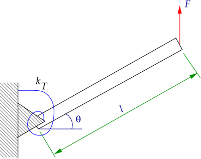
An example of a problem that involves a geometric nonlinearity is the torsional spring problem (see Figure 1).
 Figure 1. A bar attached to a torsional spring. |
We want to find the relationship between the rotation  of the bar and the applied force
  .
.
A balance of moments on the bar gives us
where  is the moment at the pinned end of the bar.
We can relate the moment  to the rotation of the spring by the constitutive equation for a torsional spring
where  is the torsional spring constant.
Therefore, we can write
If the angular displacement  is small (i.e.,
  ), we have
  . Therefore, the force-rotation relationship becomes
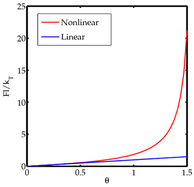
Figure 2 shows how the linear approximation compares with the nonlinear solution. The nonlinear and linear solutions are quite different beyond a rotation of around 30 degrees.
 Figure 2. Forces-rotation relationship for a bar attached to a torsional spring. |
Material nonlinearities
Material nonlinearities occur when the stress-strain or force-displacement law is not linear, or when material properties change with the applied loads.
For the torsional spring, we can introduce material nonlinearities if we assume that the constitutive equation for the spring is
In that case, the force-rotation relation becomes
If we assume small rotations, we get
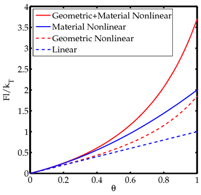
Figure 3 shows how the inclusion of material nonlinearities affects the solution.
 Figure 3. Forces-rotation relationship for a bar attached to a torsional spring (with material and geometric nonlinearities). |


