Nonlinear finite elements/Homework 11/Solutions/Problem 2
< Nonlinear finite elements < Homework 11 < SolutionsProblem 2: Billet upset forging
Given:
- Compression of cylindrical billet with rigid dies.
- No-slip contact between billet and dies.
 = 10 mm;
  = 30 mm.
 = 384.6 MPa;
  = 833.3 MPa.
- Yield stress given by
 = 1 MPa;
  = 3 MPa.
- Compressive force of 1 KN applied to die.
Solution
Part 1
Plot of final shape of billet.
This problem is solved using ANSYS 8.0. Plane182 (2-D 4-node axisymmetric element) is used to model a quarter of the billet and the die. Contac48 (2-D contact element) is used for the node to surface contact. The final shape of the billet is shown in Fig 4.
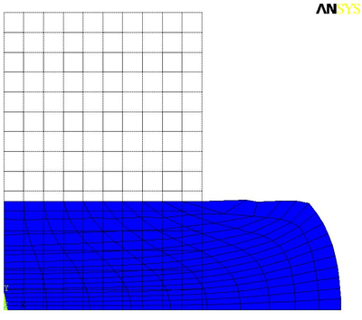 Figure 4. Deformed shape of the billet at the final load step. |
Part 2
Compare final shape with that given in Simo and Hughes.
The die moves less in the ANSYS simulation than it does in the plot shown in Simo and Hughes (p. 325, Fig. 9.8 (b)). In Simo and Hughes, the die stroke is around 20.5 mm. In our simulation, the die stroke is around 19 mm.
The top of the billet shows an undulation that indicates that contact is not being done correctly. The billet material appears to be moving through the die during deformation. Simo and Hughes do not show such an effect.
Part 3
Plot die force (N) vs. die stroke (mm).
A plot of the die force vs. the displacement at the center of the billet is shown in Fig 5.
The die stroke is (30 -  ) mm where is the displacement shown in
the plot.
) mm where is the displacement shown in
the plot.
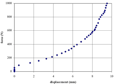 Figure 5. Billet force-displacement plot. |
Part 4
Compare plot of force vs. stroke with Simo and Hughes.
See Fig 9.8 (c) in Simo and Hughes. Our simulation shows a smaller displacement for the same load when compared with Simo and Hughes.
Part 5
Comment on volumetric locking.
The smaller displacement observed in our simulation may be an indication of volumetric locking when fully integrated PLANE182 elements are used. Underintegrated elements or assumed strain elements may alternatively be used to confirm that possibility.