Nonlinear finite elements/Homework 7
< Nonlinear finite elementsProblem 1: Index Notation
- Determine whether the following expressions are valid in index notation. If valid, identify the free indices and the dummy indices.
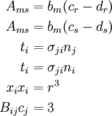
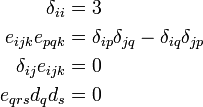
- Show the following
- The elasticity tensor is given by

where  are Lame constants,
  is the second order identity tensor, and
  is the fourth-order symmetric identity tensor.The two identity tensors are defined as
![\begin{align}
\boldsymbol{\mathit{1}} & = \delta_{ij}~\mathbf{e}_i\otimes\mathbf{e}_j \\
\boldsymbol{\mathsf{I}} & = \frac{1}{2}[\delta_{ik}\delta_{jl} + \delta_{il}\delta_{jk}]~
\mathbf{e}_i\otimes\mathbf{e}_j\otimes\mathbf{e}_k\otimes\mathbf{e}_l
\end{align}](../I/m/d16b42b7e1c1288ae3ccce9fa7db1f1c.png)
The stress-strain relation is

Show that the stress-strain relation can be written in index notation as

Write the stress-strain relations in expanded form.
Problem 2: Rotating Vectors and Tensors
Let ( ) be an orthonormal basis.Let
  be a second order tensor and
  be a vector with components
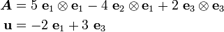
- Write out and in matrix notation.
- Find the components of the vector
 in the basis ().
 - Find the components of the vector
 in
in
the basis ().
- Find the components of the tensor
 in the orthonormal basis.
 - Rotate the basis clockwise by 30 degrees around the
 direction. Find the components of ,
  ,
,  , and
, and  in the rotated basis.
Problem 3: More Beams
Use ANSYS to solve the following problems.We want to see how the beam element BEAM188 that ANSYS provides behaves. If you use some other tool choose the equivalent element.
Beam188 is based on Timoshenko beam theory. The element uses linear shape functions for all degrees of freedom.The beam element refers to the following papers:
- Simo, J.C. and Vu-Quoc, L., 1986, "A three-dimensional finite strain rod model. Part II: Computational Aspects," Computer Methods in Applied Mechanics and Engineering, 58, pp. 79-116.
- Ibrahimbegovic, A., 1995, "On finite element implementation of geometrically nonlinear Reissner's beam theory: Three-dimensional curved beam elements," Computer Methods in Applied Mechanics and Engineering, 122, pp. 11-26.
Part A:
Consider a beam of length  = 100 in., cross-section 1 in.
  1 in., and subjected to a uniformly distributed transverse load
  lbf/in. Model one half of the beam using symmetry considerations.
Hinged-Hinged Beam
The boundary conditions are

Compute a plot for this case using Beam188 elements. What do you observe?
Clamped-Clamped Beam
The boundary conditions are

Compute a plot for this case using Beam188 elements. Comment on your plot.
You will have the save your results at the end of each load step to get the data you need.
Part B:
For this problem you will try to reproduce some of the results given in Simo and Vu Quoc (1986) and Ibrahimgbegovic (1995) using Beam188 elements.
- Simulate the unrolling of a cantilever beam from Section 4.1.1 of Ibrahimbegovic (1995) and compare your results with the results shown in the paper.
- Simulate the clamped-hinged deep circular arch from Example 7.3 of Simo and Vu Quoc (1986) and compare you results with the results shown in the paper.
- Simulate the buckling of a hinged right-angle frame under both fixed and follower loads from Example 7.4 of Simo and Vu Quoc (1986) and compare your results with those shown in the paper.