Nonlinear finite elements/Homework 5
< Nonlinear finite elementsProblem 1: Nonlinear Beam Bending
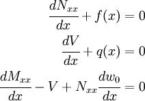
The differential equations governing the bending of straight beams are
1) Show that the weak forms of these equations can be written as
![\begin{align}
\int_{x_a}^{x_b} \cfrac{dv_1}{dx}N_{xx}~dx & =
\int_{x_a}^{x_b} v_1 f~dx + \left.v_1 N_{xx}\right|_{x_a}^{x_b}\\
\int_{x_a}^{x_b} \left[
\cfrac{dv_2}{dx}\left(\cfrac{dw_0}{dx}N_{xx}\right) -
\cfrac{d^2v_2}{dx^2}M_{xx}\right]~dx & =
\int_{x_a}^{x_b} v_2 q~dx +
\left.v_2\left(\cfrac{dw_0}{dx}N_{xx}+\cfrac{dM_{xx}}{dx}\right)
\right|_{x_a}^{x_b} -
\left.\cfrac{dv_2}{dx}M_{xx} \right|_{x_a}^{x_b}
\end{align}](../I/m/246bcd7ec2aa175a93c5bce38d888e93.png)
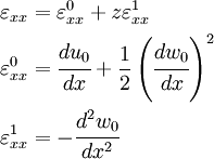
2) The von Karman strains are related to the displacements by
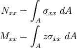
The stress and moment resultants are defined as
For a linear elastic material, the stiffnesses of the beam in extension and bending are defined as
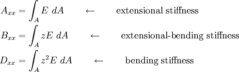
where  is the Young's modulus of the material.
Derive expressions for  and
and  in terms of the displacements
  and
and  and the extensional and bending stiffnesses of the beam assuming a linear elastic material.
3) Express the weak forms in terms of the displacements and the extensional and bending stiffnesses.
4) Assume that the approximate solutions for the axial displacement and the transverse deflection over a two noded element are given by
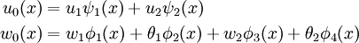
where 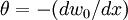 .
.
Compute the element stiffness matrix for the element.
5) Show the alternate procedure by which the element stiffness matrix can be made symmetric.
6)Derive the element tangent stiffness matrix for the element.
Problem 2: Numerical simulation
Consider the cantilever beam shown in Figure 1.
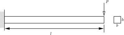 Figure 1. Cantilever beam with point load at the free end. |
The beam is made of 6061-T6 aluminum alloy.The Young's modulus of the beam is 69 GPa, the Poisson's ratio is 0.33, the tensile yield strength is 275 MPa.
The length of the beam is 5 m, the width and the thickness are both 10 cm. A point load of 10 kN is applied at the free end as shown in the figure.
- Perform a linear three-dimensional finite element analysis of the beam using 20 elements along the length and 3 elements across the thickness. Then,
- Plot the axial stress of the centroidal line as a function of distance from the fixed end.
- Plot the axial displacement of the centroidal as a function of distance from the fixed end.
- Plot the transverse displacement of the centroidal line as a function of distance from the fixed end.
- Perform a nonlinear three-dimensional finite element analysis of the beam using 20 elements along the length and 3 elements across the thickness. Then,
- Plot the axial stress of the centroidal line as a function of distance from the fixed end.
- Plot the axial displacement of the centroidal as a function of distance from the fixed end.
- Plot the transverse displacement of the centroidal line as a function of distance from the fixed end.
- Perform a linear finite element analysis of the beam using 4 beam elements. Then,
- Plot the axial stress of the centroidal line as a function of distance from the fixed end.
- Plot the axial displacement of the centroidal as a function of distance from the fixed end.
- Plot the transverse displacement of the centroidal line as a function of distance from the fixed end.
- Perform a nonlinear finite element analysis of the beam using 4 beam elements. Then,
- Plot the axial stress of the centroidal line as a function of distance from the fixed end.
- Plot the axial displacement of the centroidal as a function of distance from the fixed end.
- Plot the transverse displacement of the centroidal lineas a function of distance from the fixed end.
- Comment on your results.