Lofting technology
Astronomy is performed by location and is subject to local conditions. The shapes and sizes of observatories have changed over time, as have their altitude. The motivations for putting an observatory manned or unmanned at different altitudes has led to a great variety in lofting technology.
Technology
Def. an "organization of knowledge for practical purposes"[1] is called a technology.
"Usage notes
- Adjectives often applied to "technology": assistive, automotive, biological, chemical, domestic, educational, environmental, geospatial, industrial, instructional, medical, microbial, military, nuclear, visual, advanced, sophisticated, high, modern, outdated, obsolete, simple, complex, medieval, ancient, safe, secure, effective, efficient, mechanical, electrical, electronic, emerging, alternative, appropriate, clean, disruptive."[1]
Lofting
Def. propelling "high into the air"[2] is called lofting.
Observatories
Def. "[a] place where stars, planets and other celestial bodies are observed"[3] is called an observatory.
Horizontal coordinate system
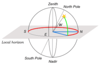
The altitude of an entity in the sky is given by the angle of the arc from the local horizon to the entity.
“The horizontal coordinate system is a celestial coordinate system that uses the observer's local horizon as the fundamental plane. This coordinate system divides the sky into the upper hemisphere where objects are visible, and the lower hemisphere where objects cannot be seen since the earth is in the way. The great circle separating hemispheres [is] called [the] celestial horizon or rational horizon. The pole of the upper hemisphere is called the zenith. The pole of the lower hemisphere is called the nadir. [4]”[5]
“The horizontal coordinates are:
- Altitude (Alt), sometimes referred to as elevation, is the angle between the object and the observer's local horizon. It is expressed as an angle between 0 degrees to 90 degrees.
- Azimuth (Az), that is the angle of the object around the horizon, usually measured from the north increasing towards the east.
- Zenith distance, the distance from directly overhead (i.e. the zenith) is sometimes used instead of altitude in some calculations using these coordinates. The zenith distance is the complement of altitude (i.e. 90°-altitude).”[5]
Altitudes
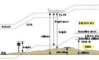
“As a general definition, altitude is a distance measurement, usually in the vertical or "up" direction, between a reference datum and a point or object. ... Although the term altitude is commonly used to mean the height above sea level of a location, in geography the term elevation is often preferred for this usage. Vertical distance measurements in the "down" direction are commonly referred to as depth.”[6]
- ”Indicated altitude -- the altimeter reading
- Absolute altitude -- altitude in terms of the distance above the ground directly below it
- True altitude -- altitude in terms of elevation above sea level
- Height -- altitude in terms of the distance above a certain point
- Pressure altitude -- altitude in terms of the air pressure
- Density altitude -- altitude in terms of the density of the air”[6].
Altitude regions
The Earth's atmosphere is divided into altitude regions:[7]
- Troposphere — surface to 8,000 m at the poles – 18,000 m at the equator, ending at the Tropopause.
- Stratosphere — Troposphere to 50 km
- Mesosphere — Stratosphere to 85 km
- Thermosphere — Mesosphere to 675 km
- Exosphere — Thermosphere to 10,000 km.[6]
Earth radius
“Because the Earth is not perfectly spherical, no single value serves as its natural radius. Distances from points on the surface to the center range from 6,353 km to 6,384 km ... Earth radius is also used as a unit of distance, especially in astronomy and geology. It is usually denoted by  . ... Earth's rotation, internal density variations, and external tidal forces cause it to deviate systematically from a perfect sphere.[8] Local topography increases the variance, resulting in a surface of unlimited complexity. ... [A]ny radius falls between the polar minimum of about 6,357 km and the equatorial maximum of about 6,378 km (≈3,950 – 3,963 mi). ... [T]he bulge at the equator shows slow variations. The bulge had been declining, but since 1998 the bulge has increased, possibly due to redistribution of ocean mass via currents.[9]"[10]
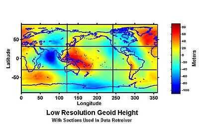
"The variation in density and crustal thickness causes gravity to vary on the surface, so that the mean sea level will differ from the ellipsoid. This difference is the geoid height, positive above or outside the ellipsoid, negative below or inside. The geoid height variation is under 110 m on Earth. The geoid height can change abruptly due to earthquakes (such as the Sumatra-Andaman earthquake) or reduction in ice masses (such as Greenland).[11]”[10]
The delta of the Mississippi river is further from the center of the Earth than the river’s origin in the state of Minnesota. As the river flows uphill, how is this possible?
Sea levels
“Mean sea level (MSL) is a measure of the average height of the ocean's surface (such as the halfway point between the mean high tide and the mean low tide); used as a standard in reckoning land elevation.[12] MSL also plays an extremely important role in aviation, where standard sea level pressure is used as the measurement datum of altitude at flight levels.”[13]
Atmospheres
Def. "a layer of gases that may surround a material body of sufficient mass,[14] and that is held in place by the gravity of the body"[15] is called an atmosphere.
Def. "[t]he gases surrounding the Earth or any astronomical body"[16] is called an atmosphere.
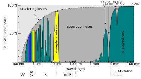
To overcome the limitations of observing in portions on either side of the visual, telescopes and spectrometers are lofted above the atmosphere for short times on board sounding rockets and balloons. Longer observing times are available with satellites placed into orbit around the Earth, the Sun, or other solar system bodies.
Absorption spectrum during atmospheric transition of electromagnetic radiation. An atmospheric transmission 'window' can be seen between 8-14 µm.
Natural electric field
The natural electric field of the Earth refers to the planet Earth having a natural direct current (DC) electric field or potential gradient from the ground upwards to the ionosphere. The static fair-weather electric field in the atmosphere is ~150 volts per meter (V/m) near the Earth's surface, but it drops exponentially with height to under 1 V/m at 30 km altitude, as the conductivity of the atmosphere increases.
The Earth is negatively charged, carrying 500,000 Coulombs (C) of electric charge (500 kC), and is at 300,000 volts (V), 300 kV,[17][18] relative to the positively charged ionosphere. There is a constant flow of electricity, at around 1350 amperes (A), and resistance of the Earth's atmosphere is around 220 Ohms.[19] This gives a power output of around 400 megawatts (MW), which is ultimately regenerated by the power of the Sun that affects the ionosphere, as well as the troposphere, causing thunderstorms. The electrical energy stored in the Earth's atmosphere is around 150 gigajoules (GJ).
The Earth-ionosphere system acts as a giant capacitor, of capacity 1.8 Farads.
The Earth's surface carries around -1 nC of electric charge per square meter.
Stonehenge
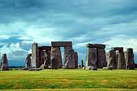
“Whatever religious, mystical or spiritual elements were central to Stonehenge, its design includes a celestial observatory function, which might have allowed prediction of eclipse, solstice, equinox and other celestial events important to a contemporary religion.[20]”[21]
“Stonehenge does not occupy a topographic high, but rather a site of intermediate elevation, such that the natural horizon, when viewed from the heel stone, is remarkably even and is sufficiently far away that its elevation above the astronomical horizon is a small angle.”[22]
“All results were registered by Professor Gowland in relation to a datum line [102.8 m] 337.4 feet above sea level.”[23]
The Giza Pyramids
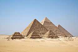
“The Great Pyramid stands on the northern edge of the Giza Plateau, [60.4 m] 198 feet above sea level”.[24]
“Since the first modern measurements of the precise cardinal orientations of the pyramids by Flinders Petrie, various astronomical methods have been proposed for the original establishment of these orientations.[25][26] It was recently proposed that this was done by observing the positions of two stars in the Plough / Big Dipper which was known to Egyptians as the thigh. It is thought that a vertical alignment between these two stars checked with a plumb bob was used to ascertain where North lay. The deviations from true North using this model reflect the accepted dates of construction.[27] Some have argued that the pyramids were laid out as a map of the three stars in the belt of Orion,[28] although this theory has been criticized by reputable astronomers.[29][30]”[31]
Aldershot Observatory
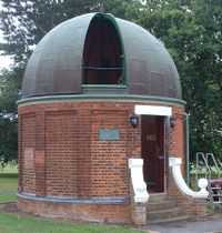
“The town is generally between 70 m and 100 m above sea level.”[32]
“The location of the observatory can hardly be considered ideal for astronomical observations, even at the time of its construction. It is at a low elevation in an essentially urban setting of an army town with many nearby buildings that date from the time of its construction.[2] It is very near a road that is lit by streetlights, although this was somewhat ameliorated by a clockwork switch inside the observatory that would turn off the nearest streetlights for about 20 minutes. This clockwork system was upgraded in 1987. As the electricity supply has been removed in 2006, this facility is no longer available. ... In its current location, the observatory will be an island in a sea of houses and some people fear that it will be targeted by vandals or, perhaps, will have to be protected with high, unsightly fences.”[33]
Tuorla Observatory
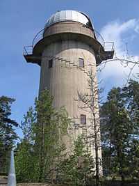
Tuorla “is located about 12 kilometres from Turku in the direction of Helsinki.”[34] The observatory is at an altitude of 60.6 m above sea level (asl).
"A new observatory was needed because the old Iso-Heikkilä Observatory close to the centre of Turku started suffering heavy light pollution from nearby city and especially industrial areas to the south of the observatory. A new place was found in Tuorla, which is one of the small villages in (former) Piikkiö municipality."[34]
"The observatory has several telescopes located around the main buildings and also international telescopes like the Nordic Optical Telescope are in use. The one meter Dall-Kirkham reflector () is the largest optical telescope in Finland."[34]
"The main area of research in Tuorla is active galactic nuclei; about half of the researchers are working on the topic. Other areas are dark matter, cosmology, astrodynamics, binary stars, solar neighborhood, solar physics and astrobiology. The optical laboratory produces high quality optics for telescopes."[34]
Arecibo Observatory
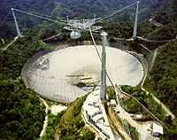
"The Arecibo Observatory is a radio telescope in the municipality of Arecibo, Puerto Rico. ... The 1,000 ft (305 m) radio telescope ... is the world's largest single-aperture telescope. It is used in three major areas of research: radio astronomy, aeronomy, and radar astronomy observations of the larger objects of the Solar System. ... The main collecting dish is 1,000 ft (305 m) in diameter, constructed inside the depression left by a karst sinkhole.[35] It contains the largest curved focusing dish on Earth, giving Arecibo the largest electromagnetic-wave-gathering capacity.[36] The dish surface is made of 38,778 perforated aluminum panels, each measuring about 3 by 6 feet (1 by 2 m), supported by a mesh of steel cables."[37]
"The telescope has three radar transmitters, with effective isotropic radiated powers of 20 TW at 2380 MHz, 2.5 TW (pulse peak) at 430 MHz, and 300 MW at 47 MHz. The telescope is a spherical reflector, not a parabolic reflector. To aim the telescope, the receiver is moved to intercept signals reflected from different directions by the spherical dish surface. A parabolic mirror would induce a varying astigmatism when the receiver is in different positions off the focal point, but the error of a spherical mirror is the same in every direction."[37]
"The receiver is located on a 900-ton platform which is suspended 150 m (500 ft) in the air above the dish by 18 cables running from three reinforced concrete towers, one of which is 110 m (365 ft) high and the other two of which are 80 m (265 ft) high (the tops of the three towers are at the same elevation). The platform has a 93-meter-long rotating bow-shaped track called the azimuth arm on which receiving antennas, secondary and tertiary reflectors are mounted. This allows the telescope to observe any region of the sky within a forty-degree cone of visibility about the local zenith (between −1 and 38 degrees of declination). Puerto Rico's location near the equator allows Arecibo to view all of the planets in the Solar System, though the round trip light time to objects beyond Saturn is longer than the time the telescope can track it, preventing radar observations of more distant objects."[37]
National Observatory of Athens

The National Observatory of Athens is 107 m asl.[38]
"[T]he new 63 cm telescope in Penteli [is] used extensively by the astronomers of the Institute."[39]
"Research areas of the [Institute of Astronomy and Astrophysics] IAA range from Solar Physics to Cosmology. The IAA also runs the 2.3 m Aristarchos telescope at Helmos Observatory and the 1.2 m telescope at Kryoneri Observatory."[40]
High altitude deserts
"Bolometers are currently the best choice for sensitive direct detection of radiation at wavelengths between 200 μm and 2 mm (e.g., Refs. 1 and 2). [...] a bolometer operates by measuring the heating due to absorbed energy [... It] is sensitive to any type of energy reaching the absorber. [... Filtering does] not prevent cosmic, gamma, and x rays from reaching a bolometer."[41]
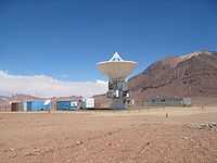
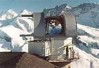
At right is the Atacama Submillimeter Telescope Experiment (ASTE). It "is a joint project between Japan and Chile to install and operate a high-precision, 10 m telescope in the Atacama desert for exploration of the southern sky in the sub-millimeter."[42] ASTE has a main reflector surface accuracy of 19 µm (RMS) and a pointing accuracy of 1.2" (RMS) [for both azimuth and elevation]."[42]
ASTE is located at Pampa la Bola (4860 masl) "in the Atacama desert of Northern Chile."[42]
Mountain tops
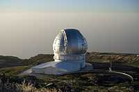
"The Gran Telescopio Canarias (meaning "Canaries Great Telescope"), also known as GranTeCan or GTC, is a 10.4 m (410 in) reflecting telescope ... at the Roque de los Muchachos Observatory on the island of La Palma, in the Canary Islands of Spain, as of July 2009. ... the telescope [is] sited on a volcanic peak 2,267 metres (7,438 ft) above sea level ... As of 2009, it is the world's largest single-aperture optical telescope.[43]"[44]
"The GTC began its preliminary observations on 13 July 2007, using 12 segments of its primary mirror, made of Zerodur glass-ceramic by the German company Schott AG. Later the number of segments was increased to a total of 36 hexagonal segments fully controlled by an active optics control system, working together as a reflective unit.[45][46] Its Day One instrumentation [is the Optical System for Imaging and low Resolution Integrated Spectroscopy] OSIRIS. Scientific observations began properly in May 2009.[47]"[44]
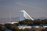
"The McMath-Pierce Solar Telescope is a 1.6-m f/54 reflecting solar telescope at Kitt Peak National Observatory in Arizona, USA. It is the largest telescope of its kind in the world and is named for astronomers Robert McMath and Keith Pierce."[48]
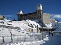
The Kulmhotel Gornergrat, atop Gorgergrat, which is both mountain and ski slope, is also home to two observatories. The Kölner Observatorium für SubMillimeter Astronomie (KOSMA) [at second right] is a 3-m radio telescope located at 3,135 m on Gornergrat near Zermatt (Switzerland) in the southern tower (nearest to the camera).
"Because of the good climatic conditions at the altitude of 3135 m (10285 ft), astronomical observatories have been located in both towers of the “Kulmhotel” at Gornergrat since 1967. In 1985, the KOSMA telescope was installed in the southern tower by the Universität zu Köln and, in the course of 1995, replaced by a new dish and mount."[49]
"The KOSMA telescope with its receivers and spectrometers was dedicated to observe interstellar and atmospheric molecular lines in the millimeter and submillimeter wavelength range. After 25 years of a successful era came to an end (June 2nd, 2010). The 3m KOSMA Radio Telescope left the Gornergrat and joined his long journey to Yangbajing / Lhasa / Tibet."[49]
"Chinese and German scientists are establishing an astronomical observatory in a Tibetan county 4,300 meters above sea level."[50]
"Tibet is an ideal location because the water deficit in its air ensures superb atmospheric transparency and creates a comparatively stable environment for research in the areas of astrophysics, high-energy and atmospheric physics."[51]
"The observatory would house a KOSMA 3-meter sub-millimeter-wave telescope, the first of its kind to be used in general astronomical observation in China."[51]
"It will boost China's research capacity in sub-millimeter astronomy and will hopefully provide a platform for astronomical experiments and training on the plateau and in the polar regions."[51]
"Sub-millimeter astronomy refers to astronomical observations carried out in the region of the electromagnetic spectrum with wavelengths from approximately 0.3 to 1 millimeter."[50]
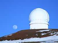
"The Canada-France-Hawaii Telescope (CFHT) is a 3.6 m optical-infrared telescope located on the summit of Mauna Kea on the island of Hawaii."[52] The CFHT is "at an altitude of 4,204 meters [...] Mauna Kea last erupted 4,000 to 6,000 years ago [~7,000 b2k]. [...] The Mauna Kea Observatories are used for scientific research across the electromagnetic spectrum from visible light to radio, and comprise the largest such facility in the world."[53]
Balloons
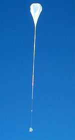

Balloons provide a long-duration platform to study any atmosphere, the universe, the Sun, and the near-Earth and space environment above as much as 99.7 % of the Earth's atmosphere. Unlike a rocket where data are collected during a brief few minutes, balloons are able to stay aloft for much longer. Balloons offer a low-cost, quick-response method for conducting scientific investigations. They are mobile, meaning they can be launched where the scientist needs to conduct the experiment, in as little as six months.
"Research balloons are balloons that are used for scientific research. They are usually (though not always) unmanned, filled with a lighter-than-air gas like helium, and fly at high altitudes."[54]
The Ultra Long Duration Balloon (ULDB) Project is developing new composite materials and a new balloon design, a standard gondola including power, global telemetry/command and an altitude control system. The ULDB is seeking to improve mission control and operations and the integration of scientific instruments. It is the potential for longer duration flights that has been the driver for the resurgence of interest in balloons by the scientific community. In recent years, the manned global ballooning attempts have called attention to the difficulty of achieving “longer”.
The MeV Auroral X-ray Imaging and Spectroscopy experiment (MAXIS) is carried aloft by a balloon for a 450 h flight from McMurdo Station, Antarctica. The MAXIS flight detected an auroral X-ray event possibly associated with the solar wind as it interacted with the upper atmosphere between January 22nd and 26th, 2000.[55]
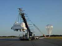
“The Balloon-borne Large Aperture Submillimeter Telescope (BLAST) is a submillimeter telescope that hangs from a high altitude balloon. It has a 2 meter primary mirror that directs light into bolometer arrays operating at 250, 350, and 500 µm.”[56]
The Columbia Scientific Balloon Facility operates and launches balloons from its remote site in Fort Sumner, New Mexico, USA. The Columbia Scientific Balloon Facility (CSBF) itself is located in Palestine, Texas, from which earlier balloon launches took place.
The various background effects OSO 1 encountered prompted the flight of similar detectors on a balloon to determine the cosmic-ray effects in the materials surrounding the detectors.
It is discovered in an early balloon flight by experimenters in the 1960s that passive collimators or shields, made of materials such as lead, actually increase the undesired background rate, due to the intense showers of secondary particles and photons produced by the extremely high energy (GeV) particles characteristic of the space radiation environment.
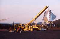
At second left "NASA's balloon-carried BLAST sub-millimeter telescope is hoisted into launch position on Dec. 25, 2012, at McMurdo Station in Antarctica on a mission to peer into the cosmos."[57] The giant helium-filled balloon is slowly drifting about 36 km above Antarctica. It was "[l]aunched on Tuesday (Dec. 25) from the National Science Foundation's Long Duration Balloon (LDB) facility ... This is the fifth and final mission for BLAST, short for the Balloon-borne Large-Aperture Submillimeter Telescope. ... "BLAST found lots of so-called dark cores in our own Milky Way — dense clouds of cold dust that are supposed to be stars-in-the-making. Based on the number of dark cores, you would expect our galaxy to spawn dozens of new stars each year on average. Yet, the galactic star formation rate is only some four solar masses per year." So why is the stellar birth rate in our Milky Way so low? Astronomers can think of two ways in which a dense cloud of dust is prevented from further contracting into a star: turbulence in the dust, or the collapse-impeding effects of magnetic fields. On its new mission, BLAST should find out which process is to blame. ... [The 1800-kilogram] stratospheric telescope will observe selected star-forming regions in the constellations Vela and Lupus."[58]
Aircraft
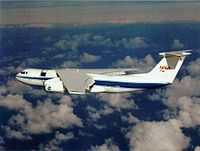
“An airborne observatory is an airplane or balloon with an astronomical telescope. By carrying the telescope high, the telescope can avoid cloud cover, pollution, and carry out observations in the infrared spectrum, above water vapor in the atmosphere which absorbs infrared radiation.”[59]
“The Gerard P. Kuiper Airborne Observatory (KAO) was a national facility operated by NASA to support research in infrared astronomy. The observation platform was a highly modified C-141A jet transport aircraft with a range of 6,000 nautical miles (11,000 km), capable of conducting research operations up to 48,000 feet (14 km). The KAO was based at the Ames Research Center, NAS Moffett Field, in Sunnyvale, California. It began operation in 1974 as a replacement for an earlier aircraft, the Galileo Observatory, a converted Convair CV-990 (N711NA)”[60].
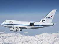
“The Stratospheric Observatory for Infrared Astronomy (SOFIA) ... is based on a Boeing 747SP wide-body aircraft that has been modified to include a large door in the aft fuselage that can be opened in flight to allow a 2.5 meter diameter reflecting telescope access to the sky. This telescope is designed for infrared astronomy observations in the stratosphere at altitudes of about 41,000 feet (about 12 km). SOFIA's flight capability allows it to rise above almost all of the water vapor in the Earth's atmosphere, which blocks some infrared wavelengths from reaching the ground. At the aircraft's cruising altitude, 85% of the full infrared range will be available.[61] The aircraft can also travel to almost any point on the Earth's surface, allowing observation from the northern and southern hemispheres."[62]
Space cannons
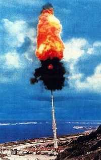
“Bull's ultimate goal was to fire a payload into space from a gun, and many have suggested that the ballistics study was offered simply to gain funding. While the speed was not nearly enough to reach orbit (less than half of the 9000 m/s delta-v required to reach Low Earth Orbit), it was a major achievement at much lower cost than most ballistic missile programs.”[63]
“The Super High Altitude Research Project (Super HARP, SHARP) was a U.S. government project conducting research into the firing of high-velocity projectiles high into the atmosphere using a two stage light gas gun, with the ultimate goal of propelling satellites into Earth orbit. Design work on the prototype space gun began as early as 1985 at the Lawrence Livermore National Laboratory in California and became operational in December 1992.[64] It is the largest gas gun in the world.[65]”[66]
“The large g-force experienced by a ballistic projectile would likely mean that a space gun would be incapable of safely launching humans or delicate instruments, rather being restricted to freight or ruggedized satellites."
"Atmospheric drag also makes it more difficult to control the trajectory of any projectile launched, subjects the projectile to extremely high forces, and causes severe energy losses that may not be easily overcome."
"The lower troposphere is the densest layer of the atmosphere, and some of these issues may be mitigated by using a space gun with a "gun barrel" reaching above it (e.g. a gun emplacement on a mountaintop)."
"A space gun, by itself, is generally not capable of placing objects into stable orbit around the planet, unless the objects are able to perform course corrections after launch.”[67]
Sounding rockets
Additional technology used to benefit astronomy includes sounding rockets which may carry gamma-ray, X-ray, ultraviolet, and infrared detectors to high altitude to view individual sources and the background for each wavelength band observed.
"A sounding rocket, sometimes called a research rocket, is an instrument-carrying rocket designed to take measurements and perform scientific experiments during its sub-orbital flight."[68]
"Sounding in the rocket context is equivalent to taking a measurement.[69]"[68]
"The rockets are used to carry instruments from 50 to 1,500 kilometres (31 to 930 mi)[70] above the surface of the Earth, the altitude generally between weather balloons and satellites (the maximum altitude for balloons is about 40 kilometres (25 mi) and the minimum for satellites is approximately 120 kilometres (75 mi)).[71] Certain sounding rockets, such as the Black Brant X and XII, have an apogee between 1,000 and 1,500 kilometres (620 and 930 mi); the maximum apogee of their class. ... NASA routinely flies the Terrier Mk 70 boosted Improved Orion lifting 270–450 kilograms (600–990 lb) payloads into the exoatmospheric region between 100 and 200 kilometres (62 and 120 mi).[72]"[68]
"A common sounding rocket consists of a solid-fuel rocket motor and a science payload.[69] The freefall part of the flight is an elliptic trajectory with vertical major axis allowing the payload to appear to hover near its apogee.[71] The average flight time is less than 30 minutes, usually between five and 20 minutes.[71] The rocket consumes its fuel on the first stage of the rising part of the flight, then separates and falls away, leaving the payload to complete the arc and return to the ground under a parachute.[69]"[68]
"Sounding rockets are advantageous for some research due to their low cost,[71] short lead time (sometimes less than six months)[69] and their ability to conduct research in areas inaccessible to either balloons or satellites. They are also used as test beds for equipment that will be used in more expensive and risky orbital spaceflight missions.[71] The smaller size of a sounding rocket also makes launching from temporary sites possible allowing for field studies at remote locations, even in the middle of the ocean, if fired from a ship.[73]"[68]
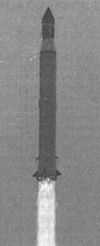
The Vertikal sounding rocket is one of many sounding rockets used by Russia and formerly by the Soviet Union, in addition to satellites, as part of an extensive solar ultraviolet and X-ray astronomy research effort. Vertikal 1 carried a Polish instrument for X-ray examinations of the Sun.[74] Vertikal 1 and 2 studied solar radiation in the wavelength range 0.1 nm to 150.0 nm with regard to X-ray emission of the quiet Sun and solar X-ray bursts.
Aircraft assisted launches
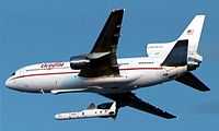
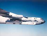
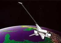
“The Pegasus is carried aloft below a carrier aircraft and launched at approximately 40,000 ft (12,000 m). The carrier aircraft provides flexibility to launch the rocket from anywhere rather than just a fixed pad. A high-altitude, winged flight launch also allows the rocket to avoid flight in the densest part of the atmosphere where a larger launch vehicle, carrying much more fuel, would be needed to overcome air friction and gravity.”[75]
"The Galaxy Evolution Explorer (GALEX) is an orbiting ultraviolet space telescope launched on April 28, 2003 [at 12:00 UTC]. A Pegasus rocket placed the craft into a nearly circular orbit at an altitude of 697 kilometres (433 mi) and an inclination to the Earth's equator of 29 degrees."[76]
"The Array of Low Energy X-ray Imaging Sensors (ALEXIS) X-ray telescopes feature curved mirrors whose multilayer coatings reflect and focus low-energy X-rays or extreme ultraviolet light the way optical telescopes focus visible light. ... The Launch was provided by the United States Air Force Space Test Program on a Pegasus Booster on April 25, 1993.[77]"[78]
Orbital rocketry
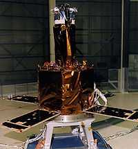
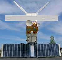
With the advent of lofting technology comes the possibility of placing an observatory as a free floating yet when necessary either a geostationary, rotating, or fixed form in orbit. The TRACE spacecraft imaged at above right is in its cleanroom during assembly prior to launch.
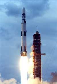
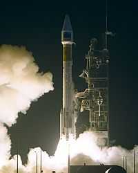
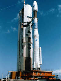
The Solar Heliospheric Observatory (SOHO) is launched at top left atop an ATLAS-IIAS expendable launch vehicle. The early Atlas is a development (an Intercontinental Ballistic Missile, ICBM) for defense as part of the mutual assured destruction (MAD) effort which helped to end the Cold War.
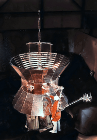
Lofting an observing system into an orbit around the Earth requires designing and testing for survival of the rocket trip upward and the orbiting technique (usually a second stage for orbital insertion). At left is an early X-ray observatory (Solrad 3), the spherical silver ball with antenna, atop a stack of satellites, being fitted with a nose cone to reduce atmospheric drag and to protect the satellites.
Once the satellite stack for Solrad 3 is securely aboard the second stage, the lofting rocket is fueled (when liquid fuel is used), and the launch commences. At right is the Thor Able Star rocket being launched by the US Air Force from Cape Canaveral, Florida, USA.
Solrad 3 is operated by the US Naval Research Laboratory beginning with its launch on June 29, 1961, through to the end of its mission on March 6, 1963. Although Solrad 3 did not successfully separate from the satellite immediately below it in the stack (Injun 1), it successfully returned solar X-ray data until late in 1961. It is not expected to re-enter the Earth's atmosphere for ~900 years.
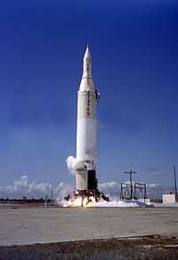
"Explorer 11 (also known as S15) was an American Earth-orbital satellite that carried the first space-borne gamma-ray telescope. This was the earliest beginning of space gamma-ray astronomy. Launched on April 27, 1961 by a Juno II rocket the satellite returned data until November 17, when power supply problems ended the science mission. During the spacecraft's seven month lifespan it detected twenty-two events from gamma-rays and approximately 22,000 events from cosmic radiation."[79]
Sun-synchronous orbital rocketry
"A Sun-synchronous orbit (sometimes called a heliosynchronous orbit[80]) is a geocentric orbit which combines altitude and inclination in such a way that an object on that orbit ascends or descends over any given Earth latitude at the same local mean solar time. The surface illumination angle will be nearly the same every time. This consistent lighting is a useful characteristic for satellites that image the Earth's surface in visible or infrared wavelengths (e.g. weather and spy satellites) and for other remote sensing satellites (e.g. those carrying ocean and atmospheric remote sensing instruments that require sunlight). For example, a satellite in sun-synchronous orbit might ascend across the equator twelve times a day each time at approximately 15:00 mean local time. This is achieved by having the osculating orbital plane precess (rotate) approximately one degree each day with respect to the celestial sphere, eastward, to keep pace with the Earth's movement around the Sun.[81]"[82]
"The uniformity of Sun angle is achieved by tuning the inclination to the altitude of the orbit ... such that the extra mass near the equator causes the orbital plane of the spacecraft to precess with the desired rate: the plane of the orbit is not fixed in space relative to the distant stars, but rotates slowly about the Earth's axis. Typical sun-synchronous orbits are about 600–800 km in altitude, with periods in the 96–100 minute range, and inclinations of around 98° (i.e. slightly retrograde compared to the direction of Earth's rotation: 0° represents an equatorial orbit and 90° represents a polar orbit).[81]"[82]
"European remote sensing satellite (ERS) was the European Space Agency's first Earth-observing satellite. It was launched on July 17, 1991 into a Sun-synchronous polar orbit at a height of 782–785 km."[83]
"ERS-1 carried an array of earth-observation instruments that gathered information about the Earth (land, water, ice and atmosphere) using a variety of measurement principles. These included:"[83]
- RA (Radar Altimeter) is a single frequency nadir-pointing radar altimeter operating in the Ku band.
- ATSR-1 (Along-Track Scanning Radiometer) is a 4 channel infrared radiometer and microwave sounder for measuring temperatures at the sea-surface and the top of clouds.
- SAR (synthetic aperture radar) operating in C band can detect changes in surface heights with sub-millimeter precision.
- Wind Scatterometer used to calculate information on wind speed and direction.
- MWR is a Microwave Radiometer used in measuring atmospheric water, as well as providing a correction for the atmospheric water for the altimeter.
"To accurately determine its orbit, the satellite included ... a Laser Retroreflector. ... The Retroreflector was used for calibrating the Radar Altimeter to within 10 cm."[83]
"Its successor, ERS-2, was launched on April 21, 1995, on an Ariane 4, from ESA's Guiana Space Centre near Kourou, French Guiana. Largely identical to ERS-1, it added additional instruments and included improvements to existing instruments including:
- GOME (Global Ozone Monitoring Experiment) is a nadir scanning ultraviolet and visible spectrometer.
- ATSR-2 included 3 visible spectrum bands specialized for Chlorophyll and Vegetation"[83]
Shuttle payloads
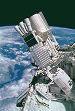
"The primary payload of mission STS-35 [December 1990] was ASTRO-1 ... The primary objectives were round-the-clock observations of the celestial sphere in ultraviolet and X-ray spectral wavelengths with the ASTRO-1 observatory, consisting of four telescopes: Hopkins Ultraviolet Telescope (HUT); Wisconsin Ultraviolet Photo-Polarimeter Experiment (WUPPE); Ultraviolet Imaging Telescope (UIT), mounted on the Instrument Pointing System (IPS). The Instrument Pointing System consisted of a three-axis gimbal system mounted on a gimbal support structure connected to a Spacelab pallet at one end and the aft end of the payload at the other, a payload clamping system for support of the mounted experiment during launch and landing and a control system based on the inertial reference of a three-axis gyro package and operated by a gimbal-mounted microcomputer.[85] The Broad Band X-Ray Telescope (BBXRT) and its Two-Axis Pointing System (TAPS) rounded out the instrument complement in the aft payload bay."[86]
The "Atmospheric Laboratory for Applications and Science (ATLAS-1) [(April 2, 1992) is] on Spacelab pallets mounted in orbiter's cargo bay. The non-deployable payload, equipped with 12 instruments from the United States, France, Germany, Belgium, Switzerland, The Netherlands and Japan, conducted studies in atmospheric chemistry, solar radiation, space plasma physics and ultraviolet astronomy. ATLAS-1 instruments were: Atmospheric Trace Molecule Spectroscopy (ATMOS); Grille Spectrometer; Millimeter Wave Atmospheric Sounder (MAS); Imaging Spectrometric Observatory (ISO); Atmospheric Lyman-Alpha Emissions (ALAE); Atmospheric Emissions Photometric Imager (AEPI); Space Experiments with Particle Accelerators (SEPAC); Active Cavity Radiometer (ACR); Measurement of Solar Constant (SOLCON); Solar Spectrum (SOLSPEC); Solar Ultraviolet Spectral Irradiance Monitor (SUSIM); and Far Ultraviolet Space Telescope (FAUST). Other payloads [aboard] included [the] Shuttle Solar Backscatter Ultraviolet (SSBUV) experiment"[87].
"The Shuttle Radar Topography Mission (SRTM) is an international research effort that obtained digital elevation models on a near-global scale from 56° S to 60° N,[88] to generate the most complete high-resolution digital topographic database of Earth prior to the release of the ASTER GDEM in 2009. SRTM consisted of a specially modified radar system that flew on board the Space Shuttle Endeavour during the 11-day STS-99 mission in February 2000, based on the older Spaceborne Imaging Radar-C/X-band Synthetic Aperture Radar (SIR-C/X-SAR), previously used on the Shuttle in 1994. To acquire topographic (elevation) data, the SRTM payload was outfitted with two radar antennas.[88] One antenna was located in the Shuttle's payload bay, the other – a critical change from the SIR-C/X-SAR, allowing single-pass interferometry – on the end of a 60-meter (200-foot) mast[88] that extended from the payload bay once the Shuttle was in space. The technique employed is known as Interferometric Synthetic Aperture Radar."[89]
"Spacelab 1 was the first Spacelab mission in orbit in the payload bay of the Space Shuttle (STS-9) between November 28 and December 8, 1983. An X-ray spectrometer, measuring 2-30 keV photons (although 2-80 keV was possible), was on the pallet. The primary science objective was to study detailed spectral features in cosmic sources and their temporal changes. The instrument was a gas scintillation proportional counter (GSPC) with ~ 180 cm2 area and energy resolution of 9% at 7 keV. The detector was collimated to a 4.5° (FWHM) FOV. There were 512 energy channels."[90]
"Spartan 1 was deployed from the Space Shuttle Discovery (STS-51G) on June 20, 1985, and retrieved 45.5 hours later. The X-ray detectors aboard the Spartan platform were sensitive to the energy range 1-12 keV. The instrument scanned its target with narrowly collimated (5' x 3°) GSPCs. There were 2 identical sets of counters, each having ~ 660 cm2 effective area. Counts were accumulated for 0.812 s into 128 energy channels. The energy resolution was 16% at 6 keV. During its 2 days of flight, Spartan-1 observed the Perseus cluster of galaxies and our galactic center region."[90]
Orbital platforms
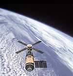
“Skylab included an Apollo Telescope Mount, which was a multi-spectral solar observatory, ... Numerous scientific experiments were conducted aboard Skylab during its operational life, and crews were able to confirm the existence of coronal holes in the Sun. The Earth Resources Experiment Package (EREP), was used to view the Earth with sensors that recorded data in the visible, infrared, and microwave spectral regions.”[91]
Heliocentric rocketry
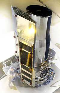
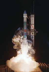
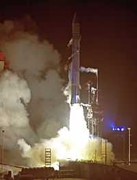
"The Spitzer Space Telescope (SST), formerly the Space Infrared Telescope Facility (SIRTF) is an infrared space observatory launched ... from Cape Canaveral Air Force Station, on a Delta II 7920H ELV rocket, Monday, 25 August 2003 at 13:35:39 UTC-5 (EDT).[92]"[93]
"Cryogenic satellites that require liquid helium (LHe, T ≈ 4 K) temperatures in near-Earth orbit are typically exposed to a large heat load from the Earth, and consequently entail large usage of LHe coolant, which then tends to dominate the total payload mass and limits mission life. Placing the satellite in solar orbit far from Earth allowed innovative passive cooling such as the sun shield, against the single remaining major heat source to drastically reduce the total mass of helium needed, resulting in an overall smaller lighter payload, with major cost savings. This orbit also simplifies telescope pointing, but does require the Deep Space Network for communications."[93]
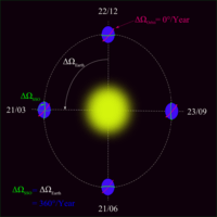
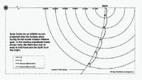
"An Earth Trailing Solar Orbit (ETSO)" causes Spitzer "to drift from Earth at a rate of about 0.1 AU per year."[94]
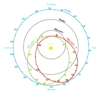
The figure at right shows the Earth-trailing solar orbit (ETSO) for Spitzer with the Earth at the origin and the Sun at left in the rotating coordinate frame "for an 8/25/03 launch projected onto the Ecliptic plane during the 62-month mission lifetime".[95]
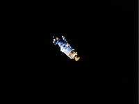
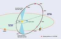
Ulysses is a "robotic space probe ... designed to study the Sun as a joint venture of NASA and the European Space Agency (ESA)."[96] To obtain an Out-Of-The-Ecliptic (OOE) heliocentric orbit Ulysses swung by Jupiter. Between 1994 and 1995 it explored both the southern (June - October 1994) and northern (June - September 1995) solar polar regions. "Between 2000 and 2001 it explored the southern solar polar regions, which gave many unexpected results. In particular the southern magnetic pole was found to be much more dynamic than the north pole and without any fixed clear location."[96] It operates over the Sun's poles for the third and last time in 2007 and 2008. "After it became clear that the power output from the spacecraft's RTG would be insufficient to operate science instruments and keep the attitude control fuel, hydrazine, from freezing, instrument power sharing was initiated. Up until then, the most important instruments had been kept online constantly, whilst others were deactivated. When the probe neared the Sun, its power-hungry heaters were turned off and all instruments were turned on.[97]"[96]
"Helios 1 and Helios 2 ... are a pair of probes launched into heliocentric orbit for the purpose of studying solar processes. ... The probes are notable for having set a maximum speed record among spacecraft at 252,792 km/h[98] (157,078 mi/h or 43.63 mi/s or 70.22 km/s or 0.000234c). Helios 2 flew three million kilometers closer to the Sun than Helios 1, achieving perihelion on 17 April 1976 at a record distance of 0.29 AU (or 43.432 million kilometers),[99] slightly inside the orbit of Mercury. Helios 2 was sent into orbit 13 months after the launch of Helios 1. ... The probes are no longer functional but still remain in their elliptical orbit around the Sun." On board, each probe carried an instrument for cosmic radiation investigation (the CRI) for measuring protons, electrons, and X-rays "to determine the distribution of cosmic rays."[100]
Exploratory rocketry
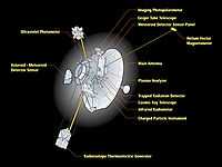


"Pioneer 10 is a 258-kilogram robotic space probe that completed the first mission to the planet Jupiter[101] and became the first spacecraft to achieve escape velocity from the Solar System."[102]
"Pioneer 10 was launched on March 2, 1972 by an Atlas-Centaur expendable vehicle from Cape Canaveral, Florida. Between July 15, 1972, and February 15, 1973, it became the first spacecraft to traverse the asteroid belt."[102]
"The International Cometary Explorer (ICE) spacecraft was originally known as [the] International Sun/Earth Explorer 3 (ISEE-3) satellite"[103].
ISEE-3 was launched on August 12, 1978. It was inserted into a "halo" orbit about the libration point some 240 Earth radii upstream between the Earth and Sun. ISEE-3 was renamed ICE (International Cometary Explorer) when, after completing its original mission in 1982, it was gravitationally maneuvered to intercept the comet P/Giacobini-Zinner. On September 11, 1985, the veteran NASA spacecraft flew through the tail of the comet. The X-ray spectrometer aboard ISEE-3 was designed to study both solar flares and cosmic gamma-ray bursts over the energy range 5-228 keV.
The instruments aboard ISEE-3 are designed to detect
- protons in the energy range 150 eV - 7 keV and electrons in the 10 eV - 1 keV range (Solar wind plasma experiment),
- Low, Medium and High-Energy Cosmic Rays (1-500 MeV/n, Z = 1-28, electrons 2-10 MeV, for Medium Energy; H to Ni, 20-500 MeV/n for High-energy),
- H-Fe 30 MeV/n - 15 GeV/n and electrons 5-400 MeV for the Cosmic-Ray Energy Spectrum experiment,
- 17 Hz - 100 kHz magnetic and electric field wave levels (Plasma Waves Spectrum Analyzer),
- low-energy solar proton acceleration and propagation processes in interplanetary space, Energetic Particle Anisotropy Spectrometer (EPAS),
- 2 keV to > 1 MeV interplanetary and solar electrons,
- radio mapping of solar wind disturbances (type III bursts) in 3-D, 30 kHz - 2 MHz,
- solar wind ion composition, 300-600 km/s, 840 eV/Q to 11.7 keV/Q, M/Q = 1.5 to 5.6,
- cosmic ray isotope spectrometer 5-250 MeV/n, Z=3-28, A=6-64 (Li-Ni),
- ground based solar studies with the Stanford ground-based solar telescope, and the comparison of these measurements with measurements of the interplanetary magnetic field and solar wind made by other experiments on this spacecraft,
- X- and gamma-ray bursts, 5-228 keV, and
- Gamma-ray bursts, 0.05-6.5 MeV direction, profile, spectrum.[104]
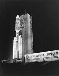
"The Voyager 1 probe was launched on September 5, 1977, from Space Launch Complex 41 at Cape Canaveral, Florida, aboard a Titan IIIE-Centaur launch vehicle."[105]
"On November 17, 1998, Voyager 1 overtook Pioneer 10 as the most distant man-made object from Earth, at a distance of 69.419 AU (1.0×10¹⁰ km). It is currently the most distant functioning space probe to receive commands and transmit information to Earth."[105]
Rocky-object rocketry
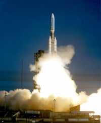
_rocket_with_Deep_Impact.jpg)
.jpg)
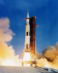
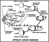
"The Apollo program was the third human spaceflight program carried out by the National Aeronautics and Space Administration (NASA), the United States' civilian space agency."[106]
"[T]he Apollo 11 mission [is] when astronauts Neil Armstrong and Buzz Aldrin landed their Lunar Module (LM) on the Moon on July 20, 1969 and walked on its surface while Michael Collins remained in [w:[lunar orbit|[lunar orbit]] in the command spacecraft, and all three landed safely on Earth on July 24. Five subsequent Apollo missions also landed astronauts on the Moon, the last in December 1972. In these six spaceflights, 12 men walked on the Moon."[106]
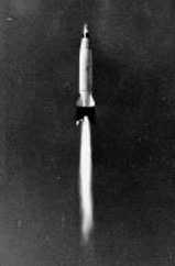
"The three-stage Saturn V was designed to send a fully fueled CSM and LM to the Moon. It was 33 feet (10.1 m) in diameter and stood 363 feet (110.6 m) tall with its 96,800-pound (43,900 kg) lunar payload. Its capability grew to 103,600 pounds (47,000 kg) for the later advanced lunar landings. The S-IC first stage burned RP-1/LOX for a rated thrust of 7,500,000 pounds-force (33,400 kN), which was upgraded to 7,610,000 pounds-force (33,900 kN). The second and third stages burned liquid hydrogen, and the third stage was a modified version of the S-IVB, with thrust increased to 230,000 lbf (1,020 kN) and capability to restart the engine for translunar injection after reaching a parking orbit.[107]"[106]
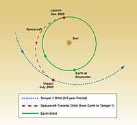
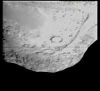
"Deep Impact is a NASA space probe launched on January 12, 2005. It was designed to study the composition of the comet interior of 9P/Tempel, by releasing an impactor into the comet. At 5:52 UTC on July 4, 2005, the impactor successfully collided with the comet's nucleus. The impact excavated debris from the interior of the nucleus, allowing photographs of the impact crater. The photographs showed the comet to be more dusty and less icy than had been expected. The impact generated a large and bright dust cloud, which unexpectedly obscured the view of the impact crater."[108]
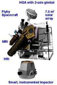
"The Flyby spacecraft is about 3.2 meters (10.5 ft) long, 1.7 meters (5.6 ft) wide and 2.3 meters (7.5 ft) high.[109][110] It includes two solar panels, a debris shield, and several science instruments for imaging, infrared spectroscopy, and optical navigation to its destination near the comet. The spacecraft also carried two cameras, the High Resolution Imager (HRI), and the Medium Resolution Imager (MRI). The HRI is an imaging device that combines a visible-light camera with a filter wheel, and an imaging infrared spectrometer called the "Spectral Imaging Module" or SIM that operates on a spectral band from 1.05 to 4.8 micrometres. It has been optimized for observing the comet's nucleus. The MRI is the backup device, and was used primarily for navigation during the final 10-day approach. It also has a filter wheel, with a slightly different set of filters."[108]
"Impact phase began nominally on June 29, five days before impact. The impactor successfully separated from the flyby spacecraft at 6:00 (6:07 Ground UTC) July 3 UTC.[111][112] The first images from the instrumented Impactor were seen two hours after separation.[113]"[108]
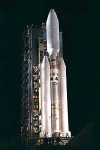
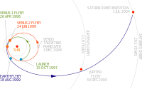
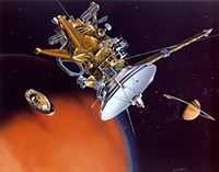
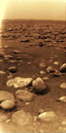
"Cassini–Huygens is ... NASA-ESA-ASI robotic spacecraft sent to the Saturn system.[114] ... It launched on October 15, 1997 on a Titan IVB/Centaur and entered into orbit around Saturn on July 1, 2004 ... On December 25, 2004, Huygens separated from the orbiter at approximately 02:00 UTC. It reached Saturn's moon Titan on January 14, 2005, when it entered Titan's atmosphere and descended downward to the surface. It successfully returned data to Earth, using the orbiter as a relay."[115]
"Cassini's instrumentation consists of: a synthetic aperture radar mapper, a charge-coupled device imaging system, a visible/infrared mapping spectrometer, a composite infrared spectrometer, a cosmic dust analyzer, a radio and plasma wave experiment, a plasma spectrometer, an ultraviolet imaging spectrograph, a magnetospheric imaging instrument, a magnetometer and an ion/neutral mass spectrometer."[115]
"Cassini released the Huygens probe on December 25, 2004, by means of a spring and spiral rails intended to rotate the probe for greater stability. It entered the atmosphere of Titan on January 14, 2005, and after a two-and-a-half-hour descent landed on solid ground. Although Cassini successfully relayed 350 of the pictures that it received from Huygens of its descent and landing site, a software error failed to turn on one of the Cassini receivers and caused the loss of the other 350 pictures."[115]
Research
Hypothesis:
- Being repelled by the Earth is a lofting technology.
Control groups

The findings demonstrate a statistically systematic change from the status quo or the control group.
“In the design of experiments, treatments [or special properties or characteristics] are applied to [or observed in] experimental units in the treatment group(s).[116] In comparative experiments, members of the complementary group, the control group, receive either no treatment or a standard treatment.[117]"[118]
Proof of concept
Def. a “short and/or incomplete realization of a certain method or idea to demonstrate its feasibility"[119] is called a proof of concept.
Def. evidence that demonstrates that a concept is possible is called proof of concept.
The proof-of-concept structure consists of
- background,
- procedures,
- findings, and
- interpretation.[120]
See also
References
- 1 2 "technology, In: Wiktionary". San Francisco, California: Wikimedia Foundation, Inc. 5 December 2014. Retrieved 2015-01-01.
- ↑ "loft, In: Wiktionary". San Francisco, California: Wikimedia Foundation, Inc. 16 December 2014. Retrieved 2015-01-01.
- ↑ "observatory, In: Wiktionary". San Francisco, California: Wikimedia Foundation, Inc. October 16, 2012. Retrieved 2012-12-05.
- ↑ James Schombert. "Earth Coordinate System". University of Oregon Department of Physics. Retrieved 19 March 2011.
- 1 2 "Horizontal coordinate system". Wikipedia (San Francisco, California: Wikimedia Foundation, Inc). April 20, 2012. http://en.wikipedia.org/wiki/Horizontal_coordinate_system. Retrieved 2012-05-14.
- 1 2 3 "Altitude, In: Wikipedia". San Francisco, California: Wikimedia Foundation, Inc. November 18, 2012. Retrieved 2012-12-05.
- ↑ "Layers of the Atmosphere". JetStream, the National Weather Service Online Weather School. National Weather Service. Retrieved 22 December 2005.
- ↑ For details see Figure of the Earth, Geoid, and Earth tide.
- ↑ Satellites Reveal A Mystery Of Large Change In Earth's Gravity Field, Aug. 1, 2002, Goddard Space Flight Center.
- 1 2 "Earth radius, In: Wikipedia". San Francisco, California: Wikimedia Foundation, Inc. December 5, 2012. Retrieved 2012-12-05.
- ↑ NASA's Grace Finds Greenland Melting Faster, 'Sees' Sumatra Quake, December 20, 2005, Goddard Space Flight Center.
- ↑ "What is "Mean Sea Level"?". Proudman Oceanographic Laboratory.
- ↑ "Sea level, In: Wikipedia". San Francisco, California: Wikimedia Foundation, Inc. September 1, 2012. Retrieved 2012-09-09.
- ↑ "Ontario Science Centre website".
- ↑ "Atmosphere, In: Wikipedia". San Francisco, California: Wikimedia Foundation, Inc. December 5, 2012. Retrieved 2012-12-05.
- ↑ "atmosphere, In: Wiktionary". San Francisco, California: Wikimedia Foundation, Inc. November 29, 2012. Retrieved 2012-12-05.
- ↑ C. Polk (1969). Coroniti SC, Hughes J.. ed. Relation of ELF Noise and Schumann Resonances to Thunderstorm Activity, In: Planetary Electrodynamics. Gordon & Breach. pp. 55-83.
- ↑ RD Hill (November-December 1971). "Spherical capacitor hypothesis of the Earth's electric field". Pure and Applied Geophysics 84 (1): 67-74. doi:10.1007/BF00875454.
- ↑ WM Farrell, MD Desch (April 2001). "Is there a Martian atmospheric electric circuit?". Journal of Geophysical Research 106 (E4): 7591-5. doi:10.1029/2000JE001271.
- ↑ GS Hawkins (1966). Stonehenge Decoded. ISBN 978-0880291477.
- ↑ "Stonehenge, In: Wikipedia". San Francisco, California: Wikimedia Foundation, Inc. November 20, 2012. Retrieved 2012-12-05.
- ↑ J. H. Robinson (March 1984). "Evidence Concerning Stonehenge as an “Observatory”". Bulletin of the American Astronomical Society 16 (3): 449.
- ↑ Morman Lockyer (2003). Stonehenge and Other British Stone Monuments Astronomically Considered. Kessinger Publishing. pp. 516.
- ↑ Petko Vidusa Nikolic, Petko Nikolic Vidusa (2005). The Great Pyramid and the Bible : Earth's Measurements. Kitchener, Canada: Mystik Book. pp. 65. ISBN 0973237147.
- ↑ Belmonte 2001
- ↑ Neugebauer 1980
- ↑ Spence 2000
- ↑ Hancock 1996:168
- ↑ Fairall 1999
- ↑ Krupp 1997b
- ↑ "Archaeoastronomy, In: Wikipedia". San Francisco, California: Wikimedia Foundation, Inc. December 5, 2012. Retrieved 2012-12-05.
- ↑ "Aldershot, In: Wikipedia". San Francisco, California: Wikimedia Foundation, Inc. December 3, 2012. Retrieved 2012-12-05.
- ↑ "Aldershot Observatory, In: Wikipedia". San Francisco, California: Wikimedia Foundation, Inc. December 26, 2011. Retrieved 2012-12-05.
- 1 2 3 4 "Tuorla Observatory, In: Wikipedia". San Francisco, California: Wikimedia Foundation, Inc. July 5. 2012. Retrieved 2012-12-05.
- ↑ David Brand (21 January 2003). "Astrophysicist Robert Brown, leader in telescope development, named to head NAIC and its main facility, Arecibo Observatory". Cornell University. Retrieved 2008-09-02.
- ↑ Frederic Castel (8 May 2000). "Arecibo: Celestial Eavesdropper". Space.com. Archived from the original on 2000-06-19. Retrieved 2008-09-02.
- 1 2 3 "Arecibo Observatory, In: Wikipedia". San Francisco, California: Wikimedia Foundation, Inc. December 8, 2012. Retrieved 2012-12-09.
- ↑ "Athens, In: Wikipedia". San Francisco, California: Wikimedia Foundation, Inc. December 5, 2012. Retrieved 2012-12-05.
- ↑ "National Observatory of Athens, In: Wikipedia". San Francisco, California: Wikimedia Foundation, Inc. December 5, 2012. Retrieved 2012-12-05.
- ↑ "The Institute for Astronomy, Astrophysics, Space Applications and Remote Sensing". Retrieved 2012-12-05.
- ↑ Adam L. Woodcraft, Rashmi V. Sudiwala, Peter A. R. Ade, Matthew J. Griffin, Elley Wakui, Ravinder S. Bhatia, Andrew E. Lange, James J. Bock, Anthony D. Turner, Minhee H. Yun, and Jeffrey W. Beeman (September 1, 2003). "Predicting the response of a submillimeter bolometer to cosmic rays". Applied Optics 42 (25): 5009-16. http://www.opticsinfobase.org/abstract.cfm?id=74103. Retrieved 2013-10-22.
- 1 2 3 Kotaro Kohno (December 2005). Chris Lidman and Danielle Alloin. ed. The Atacama Submillimeter Telescope Experiment, In: The Cool Universe: Observing Cosmic Dawn. 344. San Francisco, California USA: Astronomical Society of the Pacific. pp. 242. http://adsabs.harvard.edu/abs/2005ASPC..344..242K. Retrieved 2014-03-12.
- ↑ Irene Klotz (2009-07-24). "New telescope is world’s largest ... for now".
- 1 2 "Gran Telescopio Canarias, In: Wikipedia". San Francisco, California: Wikimedia Foundation, Inc. November 20, 2012. Retrieved 2012-12-09.
- ↑ "Tests begin on Canaries telescope". BBC. 14 July 2007.
- ↑ "Giant telescope begins scouring space". July 14, 2007.
- ↑ "El Gran Telescopio CANARIAS comienza a producir sus primeros datos científicos". IAC Press release. June 16, 2009.
- ↑ "McMath-Pierce Solar Telescope, In: Wikipedia". San Francisco, California: Wikimedia Foundation, Inc. March 16, 2012. Retrieved 2012-11-05.
- 1 2 Fachgruppe Physik (June 2, 2010). "KOSMA". Köln, Deutschland: Universität zu Köln. Retrieved 2014-03-12.
- 1 2 Wang Junjie (October 2010). "China, Germany Build Astronomical Observatory in Tibet". People's Republic of China: Chinese Academy of Sciences. Retrieved 2014-03-12.
- 1 2 3 Yan Jun (October 2010). "China, Germany Build Astronomical Observatory in Tibet". People's Republic of China: Chinese Academy of Sciences. Retrieved 2014-03-12.
- ↑ Paul Murdin (November 2000). Paul Murdin. ed. Canada-France-Hawaii Telescope, In: Encyclopedia of Astronomy and Astrophysics. Bristol: Institute of Physics. doi:10.1888/0333750888/4166. Bibcode: 2000eaa..bookE4166..
- ↑ "Canada-France-Hawaii Telescope, In: Wikipedia". San Francisco, California: Wikimedia Foundation, Inc. October 6, 2012. Retrieved 2012-12-09.
- ↑ "Research balloon, In: Wikipedia". San Francisco, California: Wikimedia Foundation, Inc. January 30, 2011. Retrieved 2012-12-05.
- ↑ R. M. Millan, R. P. Lin, D. M. Smith, K. R. Lorentzen, and M. P. McCarthy (December 2002). "X-ray observations of MeV electron precipitation with a balloon-borne germanium spectrometer". Geophysical Research Letters 29 (24): 2194-7. doi:10.1029/2002GL015922. http://www.agu.org/pubs/crossref/2002.../2002GL015922.shtml. Retrieved 2011-10-26.
- ↑ "BLAST (telescope), In: Wikipedia". San Francisco, California: Wikimedia Foundation, Inc. February 4, 2012. Retrieved 2012-06-08.
- ↑ SPACE.com (December 25, 2012). "NASA Launches Telescope-Toting Balloon from Antarctica on Christmas". SPACE.com. Retrieved 2012-12-26.
- ↑ Govert Schilling (December 26, 2012). "NASA Launches Telescope-Toting Balloon from Antarctica on Christmas". McMurdo Station: SPACE.com. Retrieved 2012-12-26.
- ↑ "Airborne observatory, In: Wikipedia". San Francisco, California: Wikimedia Foundation, Inc. July 4, 2012. Retrieved 2012-12-09.
- ↑ "Kuiper Airborne Observatory, In: Wikipedia". San Francisco, California: Wikimedia Foundation, Inc. September 1, 2012. Retrieved 2012-12-09.
- ↑ Alfred Krabbe (March, 2007). SOFIA telescope, In: ‘’Proceedings of SPIE: Astronomical Telescopes and Instrumentation’’. Munich, Germany: SPIE — The International Society for Optical Engineering. pp. 276–281.
- ↑ "Stratospheric Observatory for Infrared Astronomy, In: Wikipedia". San Francisco, California: Wikimedia Foundation, Inc. November 23, 2012. Retrieved 2012-12-09.
- ↑ "Project HARP, In: Wikipedia". San Francisco, California: Wikimedia Foundation, Inc. October 25, 2012. Retrieved 2013-12-13.
- ↑ Mark Wade. "SHARP at Encyclopedia Astronautica". Retrieved 2009-09-03.
- ↑ Scott R. Gourley (December 1996). "The Jules Verne Gun". Popular Mechanics. http://www.dodtechmatch.com/DOD/Opportunities/PrintSBIR.aspx?id=SB112-002. Retrieved 2012-03-26.
- ↑ "Super High Altitude Research Project, In: Wikipedia". San Francisco, California: Wikimedia Foundation, Inc. October 4, 2012. Retrieved 2013-12-13.
- ↑ "article title, In: Wikipedia". San Francisco, California: Wikimedia Foundation, Inc. December 9, 2011. Retrieved 2011-12-9.
- 1 2 3 4 5 "Sounding rocket, In: Wikipedia". San Francisco, California: Wikimedia Foundation, Inc. November 18, 2012. Retrieved 2012-12-05.
- 1 2 3 4 Elaine Marconi (12 April 2004). "What is a Sounding Rocket?". Research Aircraft. NASA. Retrieved 10 October 2006.
- ↑ nasa.gov NASA Sounding Rocket Program Handbook, June 2005, p. 1
- 1 2 3 4 5 "NASA Sounding Rocket Program Overview". NASA Sounding Rocket Program. NASA. 24 July 2006. Retrieved 10 October 2006.
- ↑ NASA Sounding Rocket Handbook
- ↑ "General Description of Sounding Rockets". Johns Hopkins University Sounding Rocket Program. Retrieved 10 October 2006.
- ↑ M. Hlond (May 1973). "Technical details of the Polish experiment with the geophysical rocket Vertikal-1 and Vertikal-2". Pomiary, Automat. Kontr. (Warsaw) 19 (5): 205-6. http://adsabs.harvard.edu/abs/1974STIN...7513787H. Retrieved 2012-12-09.
- ↑ "Pegasus (rocket), In: Wikipedia". San Francisco, California: Wikimedia Foundation, Inc. December 7, 2012. Retrieved 2012-12-09.
- ↑ "GALEX, In: Wikipedia". San Francisco, California: Wikimedia Foundation, Inc. November 25, 2012. Retrieved 2012-12-09.
- ↑ "ALEXIS satellite marks fifth anniversary of launch". Los Alamos National Laboratory. 23 April 1998. Retrieved 17 August 2011.
- ↑ "Array of Low Energy X-ray Imaging Sensors, In: Wikipedia". San Francisco, California: Wikimedia Foundation, Inc. December 18, 2011. Retrieved 2012-12-09.
- ↑ "Explorer 11, In: Wikipedia". San Francisco, California: Wikimedia Foundation, Inc. February 3, 2012. Retrieved 2012-12-05.
- ↑ Shcherbakova, N. N.; Beletskij, V. V.; Sazonov, V. V. - Kosmicheskie Issledovaniia, Tom 37, No. 4, p. 417 - 427, see http://adsabs.harvard.edu/abs/1999KosIs..37..417S
- 1 2 M. Rosengren: ERS-1 - An Earth Observer that exactly follows its Chosen Path, ESA Bulletin number 72, November 1992
- 1 2 "Sun-synchronous orbit, In: Wikipedia". San Francisco, California: Wikimedia Foundation, Inc. October 10, 2012. Retrieved 2012-12-05.
- 1 2 3 4 "European Remote-Sensing Satellite, In: Wikipedia". San Francisco, California: Wikimedia Foundation, Inc. November 20, 2012. Retrieved 2012-12-05.
- ↑ "Shuttle Radar Topography Mission: Mission to Map the World". Retrieved 2009-04-26.
- ↑ STS-35 Press Kit,p.31,PAO,1990
- ↑ "STS-35, In: Wikipedia". San Francisco, California: Wikimedia Foundation, Inc. November 8, 2012. Retrieved 2012-12-05.
- ↑ "STS-45, In: Wikipedia". San Francisco, California: Wikimedia Foundation, Inc. November 8, 2012. Retrieved 2012-12-05.
- 1 2 3 Nikolakopoulos 2006, p. 2
- ↑ "Shuttle Radar Topography Mission, In: Wikipedia". San Francisco, California: Wikimedia Foundation, Inc. November 16, 2012. Retrieved 2012-12-09.
- 1 2 "History of X-ray astronomy, In: Wikipedia". San Francisco, California: Wikimedia Foundation, Inc. September 19, 2012. Retrieved 2012-12-10.
- ↑ "Skylab, In: Wikipedia". San Francisco, California: Wikimedia Foundation, Inc. 19 September 2014. Retrieved 2014-10-19.
- ↑ William Harwood (December 18, 2003). "First images from Spitzer Space Telescope unveiled". Spaceflight Now. Retrieved 2008-08-23.
- 1 2 "Spitzer Space Telescope, In: Wikipedia". San Francisco, California: Wikimedia Foundation, Inc. December 2, 2012. Retrieved 2012-12-08.
- ↑ Wyatt R. Johnson. "SIM Trajectory Design". Jet Propulsion Laboratory, Pasadena, California, USA: NASA. Retrieved 2012-12-09.
- ↑ Premkumar R. Menon. "Spitzer Orbit Determination during In-Orbit Checkout Phase". Jet Propulsion Laboratory, Pasadena, California, USA: NASA. Retrieved 2012-12-09.
- 1 2 3 "Ulysses (spacecraft), In: Wikipedia". San Francisco, California: Wikimedia Foundation, Inc. December 9, 2012. Retrieved 2012-12-10.
- ↑ "ESA Portal – Ulysses scores a hat-trick".
- ↑ John Wilkinson (2012). New Eyes on the Sun: A Guide to Satellite Images and Amateur Observation. Astronomers' Universe Series. Springer. p. 37. ISBN 3-642-22838-0. http://books.google.com/books?id=Ud2icgujz0wC&pg=PA37.
- ↑ "Solar System Exploration: Missions: By Target: Our Solar System: Past: Helios 2".
- ↑ "Helios (spacecraft), In: Wikipedia". San Francisco, California: Wikimedia Foundation, Inc. November 11, 2012. Retrieved 2012-12-10.
- ↑ Fimmel, R. O.; W. Swindell, and E. Burgess (1974). SP-349/396 PIONEER ODYSSEY. NASA-Ames Research Center. ISBN SP-349. http://history.nasa.gov/SP-349/ch8.htm. Retrieved 2011-01-09.
- 1 2 "Pioneer 10, In: Wikipedia". San Francisco, California: Wikimedia Foundation, Inc. December 3, 2012. Retrieved 2012-12-05.
- ↑ "International Cometary Explorer, In: Wikipedia". San Francisco, California: Wikimedia Foundation, Inc. October 14, 2012. Retrieved 2012-12-08.
- ↑ E. Bell II (December 08, 2012). "ISEE 3". National Aeronautics and Space Administration. Retrieved 2012-12-08.
- 1 2 "Voyager 1, In: Wikipedia". San Francisco, California: Wikimedia Foundation, Inc. December 4, 2012. Retrieved 2012-12-05.
- 1 2 3 "Apollo program, In: Wikipedia". San Francisco, California: Wikimedia Foundation, Inc. December 6, 2012. Retrieved 2012-12-05.
- ↑ Orloff, Richard W. (2004). Apollo By the Numbers: A Statistical Reference. SP. 4029. NASA. http://history.nasa.gov/SP-4029/Apollo_18-11_Launch_Vehicle-Spacecraft_Key_Facts.htm.
- 1 2 3 "Deep Impact (spacecraft), In: Wikipedia". San Francisco, California: Wikimedia Foundation, Inc. November 15, 2012. Retrieved 2012-12-05.
- ↑ Lamie, William E. "Case study: NASA's "Deep Impact" employs embedded systems to score bullseye 80 million miles away". Military Embedded Systems. Retrieved May 11, 2009.
- ↑ "Deep Impact: Mission Science Q&A". NASA. Retrieved May 11, 2009.
- ↑ "Deep Impact: A Smashing Success". Deep Impact homepage. Retrieved May 11, 2009.
- ↑ Dolmetsch, Chris (July 3, 2005). "Deep Impact Launches Projectile to Blow Hole in Comet (Update1)". Bloomberg. Retrieved May 11, 2009.
- ↑ "Design, Development, and Operations of the Big Event at Tempel 1" (PDF). Deep Impact Comet Encounter. Retrieved May 11, 2009.
- ↑ "Outer Planets Flagship".
- 1 2 3 "Cassini–Huygens, In: Wikipedia". San Francisco, California: Wikimedia Foundation, Inc. December 6, 2012. Retrieved 2012-12-07.
- ↑ Klaus Hinkelmann, Oscar Kempthorne (2008). Design and Analysis of Experiments, Volume I: Introduction to Experimental Design (2nd ed.). Wiley. ISBN 978-0-471-72756-9. http://books.google.com/?id=T3wWj2kVYZgC&printsec=frontcover.
- ↑ R. A. Bailey (2008). Design of comparative experiments. Cambridge University Press. ISBN 978-0-521-68357-9. http://www.cambridge.org/uk/catalogue/catalogue.asp?isbn=9780521683579.
- ↑ "Treatment and control groups, In: Wikipedia". San Francisco, California: Wikimedia Foundation, Inc. May 18, 2012. Retrieved 2012-05-31.
- ↑ "proof of concept, In: Wiktionary". San Francisco, California: Wikimedia Foundation, Inc. November 10, 2012. Retrieved 2013-01-13.
- ↑ Ginger Lehrman and Ian B Hogue, Sarah Palmer, Cheryl Jennings, Celsa A Spina, Ann Wiegand, Alan L Landay, Robert W Coombs, Douglas D Richman, John W Mellors, John M Coffin, Ronald J Bosch, David M Margolis (August 13, 2005). "Depletion of latent HIV-1 infection in vivo: a proof-of-concept study". Lancet 366 (9485): 549-55. doi:10.1016/S0140-6736(05)67098-5. http://www.ncbi.nlm.nih.gov/pmc/articles/PMC1894952/. Retrieved 2012-05-09.
External links
- African Journals Online
- Bing Advanced search
- Google Books
- Google scholar Advanced Scholar Search
- International Astronomical Union
- JSTOR
- Lycos search
- NASA/IPAC Extragalactic Database - NED
- NASA's National Space Science Data Center
- NCBI All Databases Search
- Office of Scientific & Technical Information
- PubChem Public Chemical Database
- Questia - The Online Library of Books and Journals
- SAGE journals online
- The SAO/NASA Astrophysics Data System
- Scirus for scientific information only advanced search
- SDSS Quick Look tool: SkyServer
- SIMBAD Astronomical Database
- Spacecraft Query at NASA.
- SpringerLink
- Taylor & Francis Online
- Universal coordinate converter
- WikiDoc The Living Textbook of Medicine
- Wiley Online Library Advanced Search
- Yahoo Advanced Web Search
| |||||||||||||||||||||||||||||||||||||||||
| |||||||||||||||||||||||||||||
| |||||||||||||||||||||||||||||||||||
| |||||||||||||||||||||||||||||||||||||||||
![]() This is a research project at http://en.wikiversity.org
This is a research project at http://en.wikiversity.org
| |
Resource type: this resource is an article. |
| |
Resource type: this resource contains a lecture or lecture notes. |
| |
Educational level: this is a research resource. |
| |
Subject classification: this is an astronomy resource. |
| |
Subject classification: this is a chemistry resource . |
| |
Subject classification: this is a technology resource . |