Introduction to Combinational Logic
Course Objectives
This course will present the student with basic concepts and methods of analysis as it is applied to combinational circuits. This course assumes student has fundamental knowledge of basic circuit analysis (Ohm's Law, Node Voltage, Mesh Current, Norton, Thevenin, and Superposition).
| Course Description |
|---|
Brief Description of CourseThis course is a introductory undergraduate electrical and computer engineering course that deals with digital circuits, also known as digital logic. Students who complete this course should gain mastery in the analysis and design of combinational circuits. Message from the ContributorI will try my best to be as clear as possible when explaining concepts. However, the material in this course is best explained by performing experiments by using a prototyping board and purchasing the correct logic chips. The numbers indicates the part number of the chip, where "74" indicates a specific family of logic.
Logic chips that should be purchased at any electronics store should be: Any 7-Segment common-anode display (NTE3052 equivalent) Topics Covered
|
Number Systems and Conversions
Basic Ideas and Concepts
- The idea of a digit and what the digit can represent and its application to different numerical systems
- How to determine an equivalent numerical representation in a different numerical system
- How to add and subtract binary numbers
- Understand the differences between signed and unsigned numbers
- Understand how to represent signed numbers in binary
- How to determine the one’s and two’s complement of a binary number
Numerical Systems
We will cover the four basic numerical systems (decimal, binary, octal, and hexadecimal) and determine the conversions between each of them. A numerical system is in a simple sense, another way to represent a value of something.
| The Decimal Number System |
|---|
The Decimal Number SystemIn childhood, people are often taught the fundamentals of counting by using their fingers. Counting from one to ten is one of many milestones a child achieves on their way to becoming educated members of society. We will review these basic facts on our way to gaining an understanding of alternate number systems. The child is taught that the fingers and thumbs can be used to count from one to ten. Extending one finger represents a count of one; two fingers represents a count of two, and so on up to a maximum count of ten. No fingers (or thumbs) refers to a count of zero. The child is later taught that there are certain symbols called digits that can be used to represent these counts. These digits are, of course:
Ten, of course, is a special case, since it is comprised of two digits. Before we go deeper, we need a few fundamental definitions. DigitA digit is a symbol given to an element of a number system. RadixThe radix, or base of a counting system is defined as the number of unique digits in a given number system. Back to our elementary example. We know that our hypothetical child can count from zero to ten using their fingers and thumbs. There are ten unique digits in this counting system, therefore the radix of our elementary counting system is ten. We represent the radix of our counting system by putting the radix in subscript to the right of the digits. For example,
represents 3 in decimal (base 10). Our special case (ten) illustrates a fundamental rule of our number system that was not readily apparent - what happens when the count exceeds the highest digit? Obviously, a new digit is added, to the left of our original digit which is "worth more", or has a higher weight than our original digit. (In reality, there *always* are digits to the left; we simply choose not to write those digits to the left of the first nonzero.)
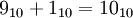
When our count exceeds the highest digit available, the next digit to the left is incremented and the original digit is reset to zero. For example:
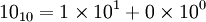
Because we are dealing with a base-10 system, each digit to the left of another digit is weighted ten times higher. Using exponential notation, we can imagine the number 10 as representing:
The fundamentals of decimal arithmetic will not be expanded on in this lecture. |


| The Binary Number System | ||||||||||||||||||||||||||||||||||||||||||||||
|---|---|---|---|---|---|---|---|---|---|---|---|---|---|---|---|---|---|---|---|---|---|---|---|---|---|---|---|---|---|---|---|---|---|---|---|---|---|---|---|---|---|---|---|---|---|---|
The Binary Number SystemIt is widely believed that the decimal system that we find so natural to use is a direct consequence of a human being's ten fingers and thumbs being used for counting purposes. One could easily imagine that a race of intelligent, six-fingered beings could quite possibly have developed a base-six counting system. From this perspective, consider the hypothesis: the most intuitive number system for an entity is that for which some natural means of counting exists. Since our focus is electronic and computer systems, we must narrow our focus from the human hand to the switch, arguably the most fundamental structure that can be used to represent a count. The switch can represent one of two states; either open, or closed. If we return to our original definition of a digit, how many digits are required to represent the possible states of our switch? Clearly, the answer is 2. We use the binary digits zero and one to represent the open and closed states of the switch. Counting in BinaryCounting in binary like base 10 can be accomplished with your fingers with some differences. In decimal base 10 each finger represents a number in the first digit 1, 2, 3, 4, 5, 6, 7, 8, 9 ,10 . When counting in binary each finger represents a separate digit so counting is more like this.
WHOA, hold on, that pattern doesn't make sense? Well when you consider that each digit in binary is worth 2 times more than the previous (right to left always) then it makes sense. Lets compare number lines.
TO BE CONTINUED Bits and bytesA bit is a digit in the binary counting system. A nybble (also spelled nibble) is a binary number consisting of four bits. A byte, or octet is a binary number consisting of eight bits. From our earlier definition of radix, the binary system has a radix of two. We use the radix in the subscript much like we do with decimals:
CountingSimilar to decimals, binary digits are weighted. Each bit is weighted twice as much as the bit to the right of it:
Counting from one to ten (base 10) in binary yields:
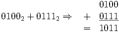
Basic binary arithmeticBinary addition, subtraction, multiplication and division operations work essentially the same as they do for decimals. For addition, you add equally-weighted bits, much like decimal addition (where you add equally-weighted digits) and carry as required to the left.
As you can see, a carry is generated in the Subtraction works just like decimal arithmetic, using borrowing as required.
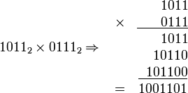
Here, a borrow is required, reducing the Multiplication is straightforward also:
Division is left as an exercise to the student [hint: use long division]. Conversion between binary and decimalWhen you consider a binary number in exponential form, you can easily perform a decimal conversion:
...simply add up the factors.
To convert from decimal to binary, you can repeatedly divide the decimal by two until the result of the division is zero. Starting from the rightmost bit, write 1 if the division has a remainder, zero if it does not. For example, to convert the decimal 74 into binary: * 74 / 2 = 37 remainder 0; -> 0 * 37 / 2 = 18 remainder 1; -> 10 * 18 / 2 = 9 remainder 0; -> 010 * 9 / 2 = 4 remainder 1; -> 1010 * 4 / 2 = 1 remainder 0; -> 01010 * 2 / 2 = 1 remainder 0; -> 001010 * 1 / 2 = 0 remainder 1; -> 1001010
| ||||||||||||||||||||||||||||||||||||||||||||||


 column which increments the
  column.
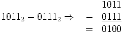
 and changing the
  .
.


| The Octal Number System |
|---|
The Octal Number SystemThe name octal implies eight, if you consider that an octagon has eight sides. Octal has a radix of eight, and uses the following octal digits:
An octal number has the subscript 8. CountingCounting from one to ten (base 10) in octal yields:
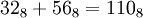
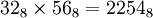
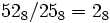
Octal arithmeticOctal arithmetic, like binary arithmetic, follows the same rules and patterns of decimal arithmetic. As an exercise, verify the following:
Conversion between binary and octalEach octal digit is representable by exactly three bits. This becomes obvious when you consider that the highest octal digit is seven, which can be represented in binary by To convert a binary number to octal, group the bits in groups of three starting from the rightmost bit and convert each triplet to its octal equivalent.
To convert an octal number to binary, simply write the equivalent bits for each octal number.
Conversion from decimal to octalThe repeated-division method described for binary will also work for octal, simply by changing the divisor to eight. To convert 67 (base 10 into octal): * 67 / 8 = 8 remainder 3; -> 3 * 8 / 8 = 1 remainder 0; -> 03 * 1 / 8 = 0 remainder 1; -> 103 Can you prove that |


 .
.

 ?
?| The Hexadecimal Number System |
|---|
The Hexadecimal Number SystemThe most commonly-used number system in computer systems is the hexadecimal, or more simply hex, system. It has a radix of 16, and uses the numbers zero through nine, as well as A through F as its digits:
Hex numbers can have the subscript 16, but more often have a leading *0x* to indicate their type.
CountingCounting from zero to twenty (base 10) in hex yields:
Hexadecimal arithmeticHex arithmetic, yet again, follows the same rules and patterns of decimal arithmetic. As an exercise, verify the following:
Conversion between hexadecimal and binaryEach hex digit is representable by exactly four bits. This becomes obvious when you consider that the highest hex digit represents fifteen, which can be represented in binary by To convert a binary number to hex, group the bits in groups of four starting from the rightmost bit and convert each group to its hex equivalent.
To convert an hex number to binary, simply write the equivalent bits for each hex number.
|


 .
.

Signed and Unsigned Numbers
We can easily represent positive or unsigned numbers in any numerical system we wish, however, when a number is not positive, we introduce the concept of signed numbers. In the binary system, there are three ways to represent a signed number: sign and magnitude, one’s complement, and two’s complement.
| Signed and Unsigned Numbers |
|---|
Representations of a Signed NumberTo represent a signed number using the sign and magnitude form in binary, we just assign the first bit of a binary number to represent whether that number is positive or negative. In sign and magnitude form, a 0 means a number is positive and a 1 means a number is negative. For example, the number below in sign and magnitude form is: Because the first digit is 1, that means that the value of all the other digits excluding the first digit is negative. To represent a signed number using the one’s complement form, we just flip all the bits of the binary number. For example, if we want to represent -2 in one’s complement form we first find the binary equivalent of that number in binary, then we flip all the bits: Therefore: Two’s complement representation is a representation of a negative number in one’s complement form and adding 1 to the final one’s complement number. So if we take the last example where: We add one to that total which gives us: |


Digitization, Logic Gates, and Symbols
Basic Ideas and Concepts
- Learn what is referred to as a "digital" circuit
- Learn the respective logic gates and symbols associated
- Learn the functionality of each logic gate
| Digitization | ||||||||||||||||||||||||||||||||||||||||||||||||||||||||||||||||||||||||||||||||||||||||||||||||||||||||||||||
|---|---|---|---|---|---|---|---|---|---|---|---|---|---|---|---|---|---|---|---|---|---|---|---|---|---|---|---|---|---|---|---|---|---|---|---|---|---|---|---|---|---|---|---|---|---|---|---|---|---|---|---|---|---|---|---|---|---|---|---|---|---|---|---|---|---|---|---|---|---|---|---|---|---|---|---|---|---|---|---|---|---|---|---|---|---|---|---|---|---|---|---|---|---|---|---|---|---|---|---|---|---|---|---|---|---|---|---|---|---|---|
DigitizationWhen we say we have a "digital" circuit, it means that we create an entire new domain that is purely represented by an analog signal. What that means is, referring back to our basic circuit of a voltage source and a resistor, we can say that the different voltage levels can represent a "low" or "high". Using electrical and computer engineering conventions, we classify a logic "high" as anywhere from 4.5 volts to 5.0 volts and a logic "low" as anywhere from 0.1 to 0.5 volts. So basically, we say that a 0 is inputted when the voltage is between 0.1-0.5 volts and a 1 if the voltage is 4.5-5 volts. Ideally however, we want 0.0 and 5.0 volts to represent 0 and 1 respectively and pictorially is represented below.
With this in mind, we can now move on and discuss logic gates which form the foundation of combinational circuits and analysis. |
| Logic Gates | ||||||||||||||||||||||||||||||||||||||||||||||||||||||||||||||||||||||||||||||||||||||||||||||||||||||||||||||||||||||||||||||||||||||||||||||||||||||||||||||||||||||
|---|---|---|---|---|---|---|---|---|---|---|---|---|---|---|---|---|---|---|---|---|---|---|---|---|---|---|---|---|---|---|---|---|---|---|---|---|---|---|---|---|---|---|---|---|---|---|---|---|---|---|---|---|---|---|---|---|---|---|---|---|---|---|---|---|---|---|---|---|---|---|---|---|---|---|---|---|---|---|---|---|---|---|---|---|---|---|---|---|---|---|---|---|---|---|---|---|---|---|---|---|---|---|---|---|---|---|---|---|---|---|---|---|---|---|---|---|---|---|---|---|---|---|---|---|---|---|---|---|---|---|---|---|---|---|---|---|---|---|---|---|---|---|---|---|---|---|---|---|---|---|---|---|---|---|---|---|---|---|---|---|---|---|---|---|---|---|
Logic GatesBelow are all the different logic symbols that are used to design and implement digital circuits.
| ||||||||||||||||||||||||||||||||||||||||||||||||||||||||||||||||||||||||||||||||||||||||||||||||||||||||||||||||||||||||||||||||||||||||||||||||||||||||||||||||||||||


 or
or 
Truth Tables and Boolean Algebra
Basic Ideas and Concepts
- What is a truth table and what can it do
- Mapping a function on a truth table and determining all possible outputs
- Applying principles of Boolean Algebra to minimize given function
- Learn how to apply minterms and maxterms expansion to a truth table
| Truth Tables | |||||||||||||||||||||||||||||||||||||||||||||||||||
|---|---|---|---|---|---|---|---|---|---|---|---|---|---|---|---|---|---|---|---|---|---|---|---|---|---|---|---|---|---|---|---|---|---|---|---|---|---|---|---|---|---|---|---|---|---|---|---|---|---|---|---|
Truth TablesA truth table is basically a representation of all the possible input combinations and the functional output of each of those combinations. It will tell you on a case-by-case basis, what will the functional output be in every input instance. We need a way to represent the 3 basic logic gates in algebraic formulas. (AND, OR, NOT) For a simple example, a truth table of the AND gate is given below.
In general the number of rows in a truth table will be
|


 , where n is the number of variables.
So in a 3 variable function where all the inputs are products, the following would be the truth table.
, where n is the number of variables.
So in a 3 variable function where all the inputs are products, the following would be the truth table.| Boolean Algebra | ||||||||||||||||||||||||||||||||||||
|---|---|---|---|---|---|---|---|---|---|---|---|---|---|---|---|---|---|---|---|---|---|---|---|---|---|---|---|---|---|---|---|---|---|---|---|---|
Boolean AlgebraWe introduce rules of Boolean Algebra to help us deal with simplifying more complex functions. The rules that should be learned are as follows.
|


 then
then 

 then
then 


Formulate a truth table for the given function below:

References and Contributors
Textbook used: Fundamentals of Digital Logic by Brown and Vranesic Copyright 2003, McGraw Hill Higher-Ed
Contributor:
User:Man4857
Vincent Nhieu, Student
California State Polytechnic University, Pomona