Inductors
The foundation of modern electrical engineering was the discovery by Faraday that when the magnetic flux through a loop of wire was varied, a voltage was set up in the wire. This process is called electromagnetic induction.
- A conductor wound in the form of a coil is called an inductor (or solenoid)
- An inductor has a strong magnetic field that has many uses
- Inductance opposes current change
- An inductor may have its inductance increased by:-
- adding more turns
- introducing an iron core through the centre of the turns
Inductance
Inductance is the property by which it opposes the change in current through a circuit.

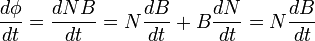
Magnetic of Inductance

Magnetic of Turns
- Φ = N B
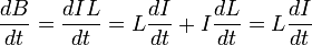
Voltage of Coil's Inductance
-
 = -ξ
= -ξ
-
Voltage of Coil's Turns
Reactance
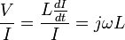
Impedance

Phase Angle
For an inductor without resistance, the voltage and current is out of phase by 90o (π/2 radians).
For an inductor with resistance, the voltage and current is out of phase by θ:
- Tan θ =
 = 2πf L/RL
- Tan θ =
When there is a change of angle, the frequency also changes. This can be used to shift the frequency:
- f = ( 2π / Tanθ ) ( RL / L )
As frequency is one over time:
- t = ( Tanθ / 2π ) (L / RL )
Frequency Response
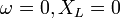 , Shorted Circuit. I = 0
 , Opened Circuit. I ‡ 0
 , Shorted Circuit. I = V / 2 RL
I - can be drawn, at certain frequency the value of current does not change with. So this circuit can be used as a high pass filter.
This article is issued from Wikiversity - version of the Sunday, July 04, 2010. The text is available under the Creative Commons Attribution/Share Alike but additional terms may apply for the media files.