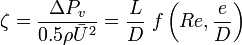
Fluid Mechanics for MAP/Energy Considerations
< Fluid Mechanics for MAPLosses and Energy consideration
|
Remember the conservation of energy equation: 
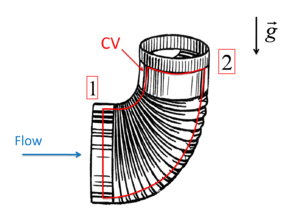
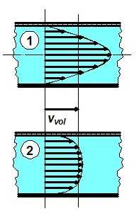
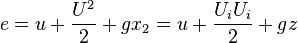 The velocity does not have necessarily a plug profile at the inlet and outlet of a control volume and the cross sectional areas might also differ at the inlet and outlet of a CV. The variations in the cross sections of flow conduits and the velocity profiles have to be accounted to calculate the correct pressure drop due to the viscous losses. Therefore, the surface integrals has to be calculated by considering these variations:  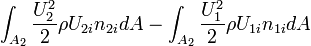 For the calculation of the profile effects one can use the kinetic energy coefficient 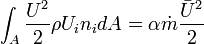
![U = 2\bar{U}\left[1 - \frac{r}{R}^{}2\right]](../I/m/1693fa7ee8663bb8ab18519bd93e517f.png)
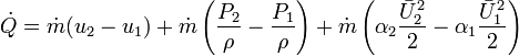
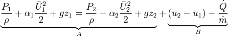 The conversion of mechanical energy (A) and the irreversible conversion and loss of mechanical energy with viscous dissipation (B) can be better distinguished. Total pressure dropFinally the total pressure drop due to viscous effects can be written as 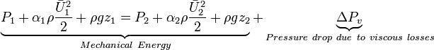 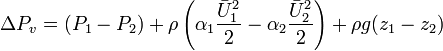 Major and minor pressure losses
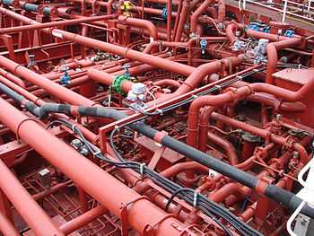
The total pressure drop consist of major losses, which are due to frictional effects in fully developed flow in constant area tubes, and minor losses, which occur at entrances, sudden area changes, bends, elbows, fittings, valves, contraction and diffusers, etc.. Major losses in pipe flows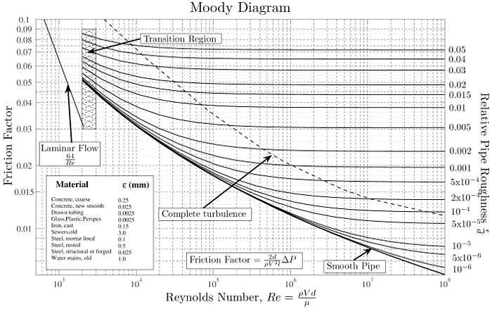 Moody diagram

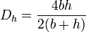
Non-circular ductsFor non circular ducts, which appears in air conditioning, heating and ventilating applications, an equivalent diameter is calculated so that correlations for circular pipes can be utilized. This equivalent diameter is called as hydraulic diameter: 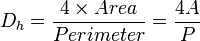
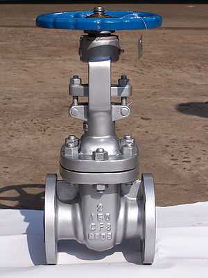
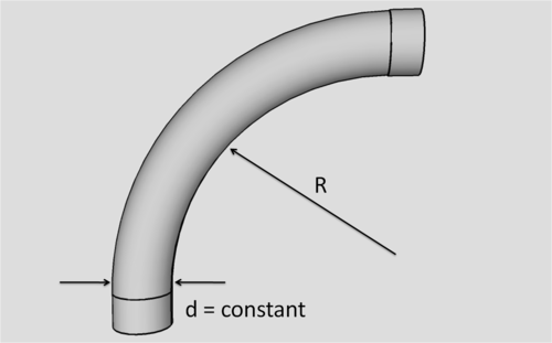
 Minor lossesFor the other components which might cause pressure drop, the loss coefficient (resistance coefficient) can similarly be defined: 
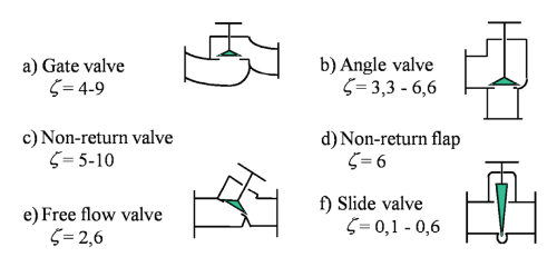
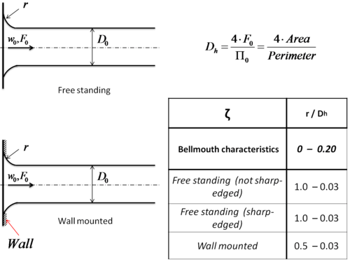
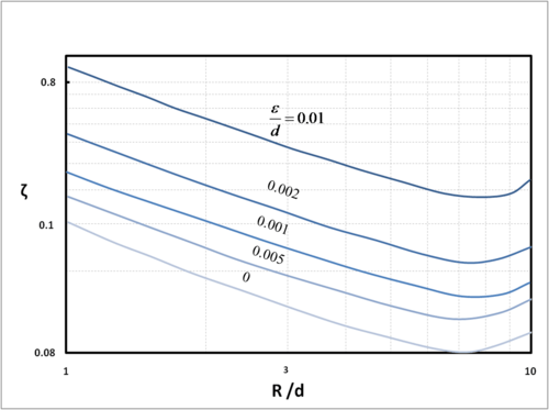
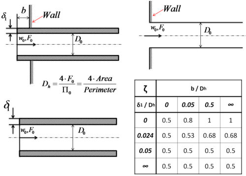
Loss coefficient of standard components
Calculation of total loss in a single pipe systemA single pipe system may have many minor losses. Since all are correlated with  ![0.5\rho\bar{U}^{2}\left[\frac{L}{D}f + \sum_{i}\zeta_{i}\right]](../I/m/4eba4acbbcda02fc64c12410b3ffea1e.png)
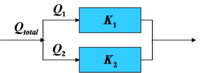
Multiple path system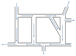 The solution for pipe network problems is often carried out by use of node and loop equations similar in many ways to that done in electrical circuits.
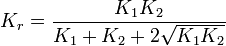
For such cases it is found useful to formulate the pressure loss as a function of the flow rate: 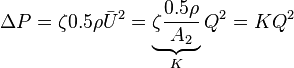 Resultant loss coefficients, Kr, for serial and parallel connectionsSerial connection: Flow rate is the same for all components 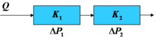  
    Design of a dry powder inhalerThe utilization of the explained concepts will be demonstrated in the class by developing an inhaler from scratch. The basic steps of the design are as follows: 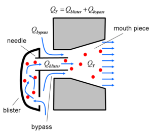 Schematics for Inhaler flow
Reference
|
 as follows:

 is the loss coefficient and f is the friction factor.
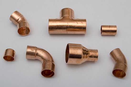

 , they can be summed into a single total system loss if the pipe has constant diameter: