Electricity/Alternating current
< Electricity| |
Resource type: this resource is a course. |
| |
Subject classification: this is an engineering resource . |
| |
Educational level: this is a secondary education resource. |
| |
Educational level: this is a tertiary (university) resource. |
This is a continuation of Introduction to Electricity I.
Alternating Current Phenomena
Capacitors
A capacitor is an electronic component designed to obey the formula
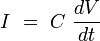
That is, the current is proportional to the time derivative of the voltage. An enormous number of important properties follow from this equation. This behavior for capacitors, along with the corresponding behaviors for inductors and resistors, are the basis for analog circuit theory.
Real-world capacitors don't follow this law exactly, but in many situations they come quite close.
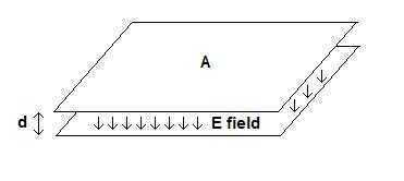
The theory behind capacitors is an application of Coulomb's Law. Suppose we have two parallel conducting plates, each of area  , with a separation distance of
  , as shown in the diagram at the right. Suppose we place a total charge of
  on the upper plate, and
  on the lower plate. (Charge relative to what? It doesn't matter.)
The charge density (coulombs per square meter) on the upper plate is  .
.
According to Coulomb's Law#The Electric Field Near a Very Large Uniformly Charged Plane, the electric field below the upper plate, arising from that plate's charge, is  , where
  is the fundamental physical constant known as the "permittivity of the vacuum". (Actually, in our case, we might use the permittivity of whatever dielectric material lies between the plates. It is common to use special materials that have an extremely high value of , in order to maximize the capacitance.) That electric field is presumed to be pointing downward.
The electric field above the lower plate, arising from that plate's charge, is  , and is presumed to be pointing upward according to that formula. We can get the downward field by changing the sign:
  . This means that the total downward field in the space between the plates is
  .
.
The amount of energy that would be released if a coulomb of charge moves from the upper plate to the lower one is the field strength times the distance (remember that electric field strength is measured in newtons per coulomb, or joules per coulomb-meter), which is

This is the voltage difference between the upper plate and the lower one.
Now suppose we push  amperes of current onto the upper plate, and remove amperes from the lower plate. That is, in ordinary electronic engineering terms, we run amperes through this device. Then increases by coulombs per second, decreases by the same amount, and so
  increases by
  coulombs per second. This means that the voltage increases by

volts per second.

We define  , the capacitance of this device, as

This is the formula for the capacitance of a capacitor made from two parallel plates separated by a distance very much smaller than the size of the plates.
The unit of capacitance is the farad, though most practical capacitors are measured in microfarads, picofarads, or even smaller. (This is because is so small.) One can see from this formula, since is a distance and is an area, that the unit of is farads per meter. Specifically, it is 8.854×10⁻¹² farads per meter.
To maximize the capacitance, capacitors have traditionally been made from thin sheets of metal foil separated by very thin layers of insulating material such as paper or mylar, and tightly rolled up into a cylinder, so that the "plates" alternate between those connected to one terminal and those connected to the other. Modern capacitors often increase from its vacuum value through the use of materials with an extremely high dielectric constant, or use other miracles of fabrication.
For further details about capacitor behavior in the real world, see Capacitor.
The Fundamental Formula
From the derivation above, the fundamental formula for the behavior of a capacitor is:
The electrical behavior of capacitors proceeds from this formula.
Another formula, if one is interested in the amount of charge, is:

Energy in a Capacitor
Suppose we have a capacitor with plate area , plate
spacing , and we have charged it to a voltage  . We know that the capacitance is
 , and the charge that we have put on it (added to the upper plate and taken from the
lower plate) is
, and the charge that we have put on it (added to the upper plate and taken from the
lower plate) is 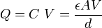 .
.
To find the energy stored in the capacitor, assume that we charged it by pouring in a constant current ,
for time  , where
  . The final charge will be
  . The voltage will
increase linearly, since
. The voltage will
increase linearly, since  , going from zero at time
  to
to
 at time
  .
.
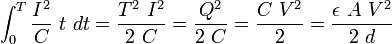
So  . The power going in at any instant is
 . The total energy at time is:
Now the electric field strength between the capacitor plates is the voltage divided by the separation distance:
 . So the energy is:
 (the volume of the capacitor)
The energy per unit volume is therefore:
The energy stored in a capacitor is actually in the electric field
between the plates. In any region of space where there is an electric
field  , there is an energy density of
  joules per cubic meter. As we will see below, there is a similar energy density arising from
magnetic fields.
joules per cubic meter. As we will see below, there is a similar energy density arising from
magnetic fields.
Inductors
An inductor is an electronic component made of (typically) coiled wire, designed to obey the formula

Differential Equations
Decimal Notation
To specify a quantity we must state both the numerical value and the units. In electrical engineering, we usually use SI units.
| Multiplier | Prefix | Abbreviation | Pronounciation |
|---|---|---|---|
| 1024 | Yotta | Y | |
| 1021 | Zetta | A | |
| 1018 | Exa | E | |
| 1015 | Peta | P | |
| 1012 | Tera | T | tê rà |
| 109 | Giga | G | jǏ;ga |
| 106 | Mega | M | měg'å |
| 103 | Kilo | k | kĭ;lo |
| 102 | Hecto | h | hêk'tǒ |
| 101 | Deka | da | dě'kå |
| 10-1 | Deci | d | dě'si |
| 10-2 | Centi | c | Sěn'ti |
| 10-3 | Mili | m | mĭl'ĭ |
| 10-6 | Micro | ų | mí'krŏ |
| 10-9 | Nano | n | nǎn'õ |
| 10-12 | Pico | p | pē' cõ |
| 10-15 | Femto | f | fěm' to |
| 10-18 | Atto | a | át' tō |
| 10-21 | Zepto | z | |
| 10-24 | Yocto | y |
The notation is based of decimal system, which uses powers of ten. The standard prefixes above are widely used multiples and submultiples of the fundamental units. Example: 50 MW ("50 megawatts") is equal to 50 x 10^6 or 50 million Watts.
Footnotes and References
- ↑ Circuits,Device and system:1976,Wiley Sons Publisher,Ralph J smith
- ↑ http://physics.nist.gov/cuu/Units/prefixes.html