Computer Support/Hardware/Interfaces
< Computer Support < HardwareThis lesson covers interfaces.
Objectives and Skills
Objectives and skills for the interfaces portion of A+ certification include:[1]
- Compare and contrast various PC connection interfaces, their characteristics and purpose.
- Physical connections
- USB 1.1 vs. 2.0 vs. 3.0
- Connector types: A, B, mini, micro
- Firewire 400 vs. Firewire 800
- SATA1 vs. SATA2 vs. SATA3, eSATA
- Other connector types
- VGA
- HDMI
- DVI
- Audio
- Analog
- Digital (Optical connector)
- RJ-45
- RJ-11
- Thunderbolt
- USB 1.1 vs. 2.0 vs. 3.0
- Wireless connections
- Bluetooth
- RF
- IR
- NFC
- Characteristics
- Analog
- Digital
- Distance limitations
- Data transfer speeds
- Quality
- Frequencies
- Physical connections
Readings
- Read Wikipedia: Electrical connector.
- Read Wikipedia: USB.
- Read Wikipedia: IEEE 1394.
- Read Wikipedia: Serial ATA.
- Read Wikipedia: Video graphics array.
- Read Wikipedia: HDMI.
- Read Wikipedia: Digital visual interface.
- Read Wikipedia: Balanced audio.
- Read Wikipedia: S/PDIF.
- Read Wikipedia: AES3.
- Read Wikipedia: Modular connector.
- Read Wikipedia: Registered jack.
- Read Wikipedia: Thunderbolt (interface).
- Read Wikipedia: Wireless network.
- Read Wikipedia: Bluetooth.
- Read Wikipedia: Wi-fi.
- Read Wikipedia: Infrared Data Association.
- Read Wikipedia: Near field communication.
- Read Wikipedia: Signal (electrical engineering.
- Read Wikipedia: Analog signal.
- Read Wikipedia: Digital signal.
Multimedia
- Watch YouTube: Computer Interface Speeds and Distances - CompTIA A+ 220-901: 1.7.
- Watch YouTube: Wireless Interface Speeds and Distances - CompTIA A+ 220-901 - 1.7.
- Watch YouTube: Connection Characteristics - CompTIA A+ 220-901 - 1.7.
Activities
- Read Sparkfun Analog vs. Digital Tutorial
- Read Going The Distance - A Guide to Maximum Cable Lengths
Lesson Summary
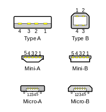
Standard, mini, and micro USB plugs (not to scale). The white areas in the drawings represent hollow spaces. As the plugs are shown here, the USB logo (with optional letter A or B) is on the top of the overmold in all cases. Pin numbering (looking into receptacles) is mirrored from plugs, such that pin 1 on plug connects to pin 1 on the receptacle.
- USB was designed to standardize the connection of computer peripherals (including keyboards, pointing devices, digital cameras, printers, portable media players, disk drives and network adapters) to personal computers, both to communicate and to supply electric power. It has become commonplace on other devices, such as smartphones, PDAs and video game consoles. USB has effectively replaced a variety of earlier interfaces, such as serial and parallel ports, as well as separate power chargers for portable devices.[2]
- The data cables for USB 1.x and USB 2.x use a twisted pair to reduce noise and crosstalk. USB 3.0 cables contain twice as many wires as USB 2.x to support SuperSpeed data transmission, and are thus larger in diameter.[2]
- Released in January 1996, USB 1.0 specified data rates of 1.5 Mbit/s (Low Bandwidth or Low Speed) and 12 Mbit/s (Full Bandwidth or Full Speed).[2]
- The USB 1.1 standard specifies that a standard cable can have a maximum length of 5 meters with devices operating at Full Speed (12 Mbit/s), and a maximum length of 3 meters with devices operating at Low Speed (1.5 Mbit/s).[2]
- USB 2.0 was released in April 2000, adding a higher maximum signaling rate of 480 Mbit/s called High Speed, in addition to the USB 1.x Full Speed signaling rate of 12 Mbit/s.[2]
- USB 2.0 provides for a maximum cable length of 5 meters for devices running at Hi Speed (480 Mbit/s). [2]
- USB 3.0 adds the new transfer mode SuperSpeed (SS) that can transfer data at up to 5 Gbit/s (625 MB/s), which is about ten times as fast as the USB 2.0 standard. Manufacturers often distinguish USB 3.0 connectors from their USB 2.0 counterparts by blue color-coding of the receptacles and plugs and by the initials SS.[2]
- The USB 3.0 standard does not directly specify a maximum cable length, requiring only that all cables meet an electrical specification: for copper cabling with AWG 26 wires the maximum practical length is 3 meters (9.8 ft).[2]
- FireWire is Apple's name for the IEEE 1394 High Speed Serial Bus. FireWire can connect up to 63 peripherals in a tree or daisy-chain topology, and is designed to support plug and play and hot swapping. IEEE 1394 was the High-Definition Audio-Video Network Alliance (HANA) standard connection interface for A/V (audio/visual) component communication and control. FireWire is also available in wireless, fiber optic, and coaxial versions using the isochronous protocols.[3]
- The original release of IEEE 1394-1995 specified what is now known as FireWire 400. It can transfer data between devices at 100, 200, or 400 Mbit/s full-duplex data rates. These different transfer modes are commonly referred to as S100, S200, and S400.[3]
- Cable length is limited to 4.5 metres (14.8 ft), although up to 16 cables can be daisy chained using active repeaters; external hubs, or internal hubs are often present in FireWire equipment. The S400 standard limits any configuration's maximum cable length to 72 metres (236 ft).[3]
- IEEE 1394b-2002 introduced FireWire 800, which supports a transfer rate of 786.432 Mbit/s full-duplex. It is backwards compatible with the slower rates and 6-conductor alpha connectors of FireWire 400. However, while the IEEE 1394a and IEEE 1394b standards are compatible, FireWire 800's connector, referred to as a beta connector, is different from FireWire 400's alpha connectors, making legacy cables incompatible. A bilingual cable allows the connection of older devices to the newer port. [3]
- The full IEEE 1394b specification supports data rates up to 3200 Mbit/s over beta-mode or optical connections up to 100 metres (330 ft) in length. Standard Category 5e unshielded twisted pair supports 100 metres (330 ft) at S100.[3]
- The original release of IEEE 1394-1995 specified what is now known as FireWire 400. It can transfer data between devices at 100, 200, or 400 Mbit/s full-duplex data rates. These different transfer modes are commonly referred to as S100, S200, and S400.[3]
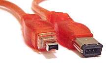
4-conductor (left) and 6-conductor (right) FireWire 400 alpha connectors
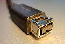
A 9-pin FireWire 800 connector
- Serial AT Attachment (Serial ATA or SATA) is a computer bus interface that connects host bus adapters to mass storage devices such as hard disk drives, optical drives, and solid-state drives. SATA succeeded the older Parallel ATA (PATA) standard,[a] offering several advantages over the older interface: reduced cable size and cost (seven conductors instead of 40 or 80), native hot swapping, faster data transfer through higher signaling rates, and more efficient transfer through an (optional) I/O queuing protocol.[4]
- SATA cables can have lengths up to 1 metre (3.3 ft), and connect one motherboard socket to one hard drive.[4]
- Revision 1.0a was released on January 7, 2003. First-generation SATA interfaces, now known as SATA 1.5 Gbit/s, communicate at a rate of 1.5 Gbit/s.[4]
- SATA revision 2.0 was released in April 2004, and run with a native transfer rate of 3.0 Gbit/s. All SATA data cables meeting the SATA spec are rated for 3.0 Gbit/s and handle modern mechanical drives without any loss of sustained and burst data transfer performance. However, high-performance flash-based drives can exceed the SATA 3 Gbit/s transfer rate.[4]
- The full 3.0 standard was released on May 27, 2009. Third-generation SATA interfaces run with a native transfer rate of 6.0 Gbit/s; taking 8b/10b encoding into account, the maximum uncoded transfer rate is 4.8 Gbit/s (600 MB/s). The theoretical burst throughput of SATA 6.0 Gbit/s is double that of SATA revision 2.0. It is backward compatible with SATA 3 Gbit/s.[4]
- Standardized in 2004, eSATA (e standing for external) provides a variant of SATA meant for external connectivity. It uses a more robust connector, longer shielded cables, and stricter (but backward-compatible) electrical standards.[4]
- Maximum cable length increased to 2 metres[4]
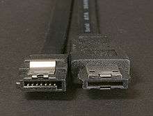
SATA (left) and eSATA (right) connectors
SATA connector on a 3.5-inch hard drive, with data pins on the left, and power pins on the right. The two different pin lengths ensure a specific mating order; the longer lengths are ground pins and make contact first.
- A Video Graphics Array (VGA) connector is a three-row 15-pin DE-15 connector. The 15-pin VGA connector is found on many video cards, computer monitors, and high definition television sets. On laptop computers or other small devices, a mini-VGA port is sometimes used in place of the full-sized VGA connector. VGA connectors and cables carry analog component RGBHV (red, green, blue, horizontal sync, vertical sync) video signals, and VESA Display Data Channel (VESA DDC) data. The VGA interface is not engineered to be hotpluggable, although in practice this can be done and usually does not cause damage to the hardware or other problems. However, nothing in the design ensures that the ground pins make a connection first and break last, so hotplugging may introduce surges in signal lines which may or may not be adequately protected against. Also, depending on the hardware and software, detecting a monitor being connected might not work properly in all cases.
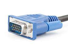
A VGA cable with DE-15 male connector
- HDMI (High-Definition Multimedia Interface) is a proprietary audio/video interface for transferring uncompressed video data and compressed or uncompressed digital audio data from an HDMI-compliant source device, such as a display controller, to a compatible computer monitor, video projector, digital television, or digital audio device. HDMI is a digital replacement for analog video standards. The maximum pixel clock rate for HDMI 1.0 was 165 MHz, which was sufficient to allow 1080p and WUXGA (1920×1200) at 60 Hz. HDMI 1.3 increased that to 340 MHz, which allows for higher resolution (such as WQXGA, 2560×1600) across a single digital link. There are five HDMI connector types. Type A/B are defined in the HDMI 1.0 specification, type C is defined in the HDMI 1.3 specification, and type D/E are defined in the HDMI 1.4 specification.[5]
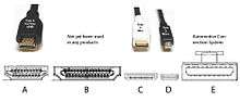
connector types for HDMI
- Digital Visual Interface (DVI) is used to connect a video source, such as a graphics card to a display device, such as a computer monitor. It was developed with the intention of creating an industry standard for the transfer of digital video content. DVI is designed to transmit uncompressed digital video and can be configured to support multiple modes such as DVI-D (digital only), DVI-A (analog only), or DVI-I (digital and analog). Featuring support for analog connections, the DVI specification is compatible with the VGA interface. Although DVI is predominantly associated with computers, it is sometimes used in other consumer electronics such as television sets, video game consoles,[citation needed] and DVD players.[6]

Male DVI connector pins (view of plug)
- A phone connector, also known as phone jack, audio jack or jack plug, is a common family of connector typically used for analog signals, primarily audio. It is cylindrical in shape, typically with two, three or four contacts. Three-contact versions are known as TRS connectors, where T stands for "tip", R stands for "ring" and S stands for "sleeve". Similarly, two- and four-contact versions are called TS and TRRS connectors respectively. Normally, 3.5 mm three-conductor sockets are used in computer sound cards for stereo output.[7]
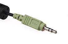
A 3.5 mm plug for computer audio
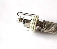
A pair of phone connectors: A phone plug (right) is inserted in a phone socket (left). For terms, see section Other terms.
- S/PDIF (Sony/Philips Digital Interface Format) is a type of digital audio interconnect used in consumer audio equipment to output audio over reasonably short distances. The signal is transmitted over either a coaxial cable with RCA connectors or a fibre optic cable with TOSLINK connectors. S/PDIF interconnects components in home theatres and other digital high fidelity systems.[8]
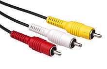
RCA Plugs for composite video (yellow) and stereo audio (white and red)
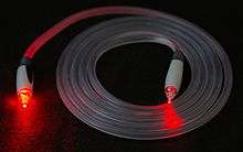
A TOSLINK fiber optic audio cable being illuminated on one end
- A modular connector is an electrical connector that was originally designed for use in telephone wiring, but has since been used for many other purposes. Probably the most well known applications of modular connectors are for telephone jacks and for Ethernet jacks, both of which are nearly always modular connectors.[9]
- RJ11 is a physical interface often used for terminating telephone wires. It is probably the most familiar of the registered jacks, being used for single line POTS (Plain Old Telephone System) telephone jacks in most homes across the world. Cables sold as RJ11 often actually use 6P4C (6 position 4 contact) RJ14 connectors, with four wires running to a central junction box. Two of its six possible contact positions connect tip and ring, and the other two contact positions are then unused.[10]
- Although commonly referred to as an RJ45 in the context of Ethernet and category 5 cables, it is incorrect to refer to a generic 8P8C (8 position 8 contact) connector as an RJ45. 8P8C are commonly used in computer networking and telephone applications, where the plug on each end is an 8P8C modular plug wired according to a TIA/EIA standard. Most wired Ethernet network communications today are carried over Category 5e or Category 6 cable with an 8P8C modular plug crimped on each end. The 8P8C modular connector is also used for RS-232 serial interfaces according to the EIA/TIA-561 standard. This application is common as a console interface on network equipment such as switches and routers. Other applications include other networking services such as ISDN and T1.[11]
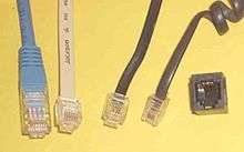
Left to right, modular connectors: 8P8C plug, 6P6C plug, 6P4C plug, 4P4C plug, 6P6C jack.
- Thunderbolt combines PCI Express (PCIe) and DisplayPort (DP) into one serial signal, and additionally provides DC power, all in one cable. Up to six peripherals may be supported by one connector through various topologies. Though Thunderbolt was originally conceived as an optical technology, Intel switched to electrical connections to reduce costs and to supply up to 10 watts of power to connected devices. Thunderbolt 1 and 2 use the same connector as Mini DisplayPort (MDP), while Thunderbolt 3 uses USB Type-C.[12]
- At the physical level, the bandwidth of Thunderbolt 1 and Thunderbolt 2 are identical, and Thunderbolt 1 cabling is thus compatible with Thunderbolt 2 interfaces. At the logical level, Thunderbolt 2 enables channel aggregation, whereby the two previously separate 10 Gbit/s channels can be combined into a single logical 20 Gbit/s channel. Intel claims Thunderbolt 2 will be able to transfer a 4K video while simultaneously displaying it on a discrete monitor.
- Thunderbolt 3 doubles the bandwidth to 40 Gbit/s, halves power consumption, and simultaneously drives two external 4K displays at 60 Hz (or a single external 4K display at 120 Hz)
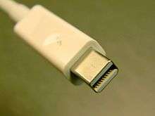
A Thunderbolt connector (v1/v2).
- Wireless communication is the transfer of information between two or more points that are not connected by an electrical conductor. The most common wireless technologies use radio. With radio waves distances can be short, such as a few meters for television or as far as thousands or even millions of kilometers for deep-space radio communications. It encompasses various types of fixed, mobile, and portable applications, including two-way radios, cellular telephones, personal digital assistants (PDAs), and wireless networking. Other examples of applications of radio wireless technology include GPS units, garage door openers, wireless computer mice, keyboards and headsets, headphones, radio receivers, satellite television, broadcast television and cordless telephones.[13]
- Bluetooth is a wireless technology standard for exchanging data over short distances (using short-wavelength UHF radio waves in the ISM (industrial, scientific, medical) band from 2.4 to 2.485 GHz) from fixed and mobile devices, and building personal area networks (PANs).[14]
- Bluetooth exists in many products, such as telephones, tablets, media players, robotics systems, handheld, laptops and console gaming equipment, and some high definition headsets, modems, and watches. The technology is useful when transferring information between two or more devices that are near each other in low-bandwidth situations. Bluetooth is commonly used to transfer sound data with telephones (i.e., with a Bluetooth headset) or byte data with hand-held computers (transferring files).
- Bluetooth protocols simplify the discovery and setup of services between devices. Bluetooth devices can advertise all of the services they provide. This makes using services easier, because more of the security, network address and permission configuration can be automated than with many other network types.
- Wi-Fi is a wireless local area network that enables portable computing devices to connect easily to the Internet. Standardized as IEEE 802.11 a,b,g,n, Wi-Fi approaches speeds of some types of wired Ethernet. Wi-Fi has become the de facto standard for access in private homes, within offices, and at public hotspots.[15]
- The 802.11a standard operates in the 5 GHz band with a maximum net data rate of 54 Mbit/s, plus error correction code, which yields realistic net achievable throughput in the mid-20 Mbit/s.[16]
- The 802.11b standard has a maximum raw data rate of 11 Mbit/s in the 2.4 GHz band. 802.11b products appeared on the market in early 2000.[17]
- The 802.11g standard works in the 2.4 GHz band and operates at a maximum bit rate of 54 Mbit/s exclusive of forward error correction codes, or about 22 Mbit/s average throughput. 802.11g hardware is fully backward compatible with 802.11b hardware.[18]
- 802.11n came out in 2009 and added multiple-input multiple-output antennas (MIMO). 802.11n operates on both the 2.4 GHz and the lesser-used 5 GHz bands. Support for 5 GHz bands is optional. It operates at a maximum net data rate from 54 Mbit/s to 600 Mbit/s.[19]
- The Infrared Data Association (IrDA) is an industry-driven interest group that was founded in 1993 by around 50 companies. IrDA provides specifications for a complete set of protocols for wireless infrared communications, and the name "IrDA" also refers to that set of protocols. The main reason for using IrDA had been wireless data transfer over the “last one meter” using point-and-shoot principles. Main characteristics of this kind of wireless optical communication is physically secure data transfer, line-of-sight (LOS) and very low bit error rate (BER) that makes it very efficient.[20]
- IrDA was popular on PDAs, laptops and some desktops from the late 1990s through the early 2000s. However, it has been displaced by other wireless technologies such as Wi-Fi and Bluetooth, favored because they don't need a direct line of sight and can therefore support hardware like mice and keyboards. It is still used in some environments where interference makes radio-based wireless technologies unusable.
- IrDA has a transfer speed of about 4 Mbit/s.
- Near field communication (NFC) is a set of short-range wireless technologies, typically requiring a separation of 10 cm or less. NFC operates at 13.56 MHz at 106 Kbit/s, 212 Kbit/s, or 424 Kbit/s. NFC always involves an initiator and a target; the initiator actively generates an RF field that can power a passive target. This enables NFC targets to take very simple form factors such as unpowered tags, stickers, key fobs, or cards. NFC peer-to-peer communication is possible, provided both devices are powered.[21]
- Signals can be either analog, in which case the signal varies continuously according to the information, or digital, in which case the signal varies according to a series of discrete values representing the information.[22]
- An analog signal uses some property of the medium to convey the signal's information. In an electrical signal, the voltage, current, or frequency of the signal may be varied to represent the information.[23]
- A digital signal is a discrete-time signal for which not only the time but also the amplitude has discrete values; in other words, its samples take on only values from a discrete set (a countable set that can be mapped one-to-one to a subset of integers).[24]
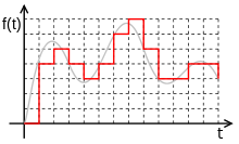
Digital signal (red) is the sampled and rounded representation of the grey analog signal
References
- ↑ CompTIA: A+ Certification Exam Objectives - Exam 220-901
- 1 2 3 4 5 6 7 8 Wikipedia: USB
- 1 2 3 4 5 Wikipedia: IEEE 1394
- 1 2 3 4 5 6 7 Wikipedia: Serial ATA
- ↑ Wikipedia: HDMI
- ↑ Wikipedia: Digital Visual Interface
- ↑ Wikipedia: Phone connector (audio)
- ↑ Wikipedia: S/PDIF
- ↑ Wikipedia: Modular connector
- ↑ Wikipedia: Modular connector#6P6C
- ↑ Wikipedia: Modular connector#8P8C
- ↑ Wikipedia: Thunderbolt (interface)
- ↑ Wikipedia: Wireless
- ↑ Wikipedia: Bluetooth
- ↑ Wikipedia: Wi-fi
- ↑ Wikipedia: IEEE 802.11
- ↑ Wikipedia: IEEE 802.11
- ↑ Wikipedia: IEEE 802.11
- ↑ Wikipedia: IEEE 802.11
- ↑ Wikipedia: Infrared Data Association
- ↑ Wikipedia: Near Field Communication
- ↑ Introduction to Electrical Engineering#Signal processing
- ↑ Wikipedia: Analog signal
- ↑ Wikipedia: Digital signal (signal processing)
This article is issued from Wikiversity - version of the Monday, March 14, 2016. The text is available under the Creative Commons Attribution/Share Alike but additional terms may apply for the media files.