Arduino/Junk pile stepper motor survey
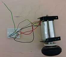
< ArduinoThe purpose of this page is to record the wiring of junked stepper motors to arduino motor shields.
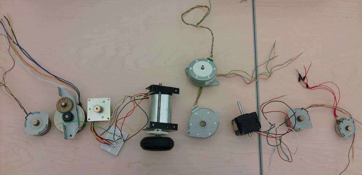
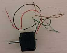
Stepper motors have 4 or more wires going into them. Not all motors with 4 or more wires are stepper motors. Typically these motors do not settle down and display a constant ohm value. Instead the resistance reading go to zero or infinity. Switching the polarity of the probes measuring resistance causes different resistance values.
Next Steps
- Attach motor shield to larger power source .. 9-12volts .. perhaps up to 1.5amps. See how motor strength improves and how chips on motor shield heat up.
- Get spark fun motor shields working .. suppose to handle more power
- Count teeth on the gears to see if there are standards that can be leveraged
- Research PC power supply specifications to see if they are going to be useful
- Figure out how fast the motors can rotate .. some seem pretty slow .. this may be due to the stepper motor program or sketch.
Individual Motor Details
| Pairs | Motor Description | Motor Thumb |
|---|---|---|
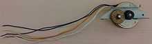
| orange/blue, purple/red |
4 wire
|
 |
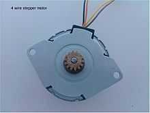
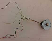
| orange/yellow, brown/black |
4 wire
|
 |
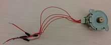
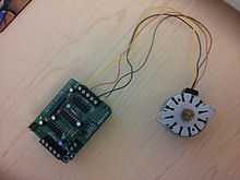
brown/red, blue/yellow
|
5 wire
|
 |
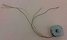
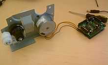
brown/red, white/green
|
5 wire
|
 |
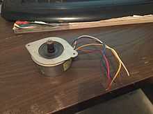
yellow/orange, green/gray
|
5 wire
|
 |
blue/yellow, gray/purple
|
8 wire
|
 |
black/brown, yellow/orange
|
6 wire
|
 |
black/blue, orange/yellow
|
6 wire
|
 |
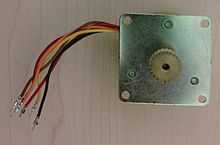
| orange/yellow, brown/black |
4 wire
|
  |
| orange/yellow, brown/black |
4 wire
|
 |
This article is issued from Wikiversity - version of the Sunday, April 05, 2015. The text is available under the Creative Commons Attribution/Share Alike but additional terms may apply for the media files.