Arduino/CloverDisplayLtd
< ArduinoLiquid Crystal Display (LCD) Inspection/Research
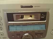
This LCD panel was taken out of a Panasonic fax machine. Ten wires are connected to the ten pins on the board of the LCD. Searching the web for specifications using the information printed on the board (Clover Display Ltd. M235 v4.1) was unsuccessful being unable to find the specific model. Fortunately, there is a tutorial on hacking a LCD to the Arduino in the example libraries of the arduino.exe under 'Liquid Crystal'. "LCDs have a parallel interface, meaning that the microcontroller has to manipulate several interface pins at once to control the display. The interface consists of the following pins:"
- Register select (RS) pin - controls where in the LCD's memory that data is written to. ie. Data register - holds what goes on the screen, or an instruction register - where the LCD controller looks for instructions on what to do next.
- Read/Write (R/W) pin - selects reading or writing mode
- Enable pin - allows writing to the registers
- 8 Data pins (D0-D7) - have states (high or low) that are the bits that are written to a register when writing is enabled, or values that are readable when reading is enabled.
- Display Contrast pin (Vo) - controls contrariety or variance
- Power Supply pins (+5V and GND) - powers/energizes the LCD
- LED Backlight (Bklt+ and Bklt-) - Turn on and off glowing background
Problem Statement
"The LiquidCrystal library allows you to control LCD displays that are compatible with the Hitachi HD44780 driver. There are many of them out there, and you can usually tell them by the 16-pin interface." This Clover LCD only has ten pins, so will it be compatible with this Arduino library example? Luckily, only ten of the sixteen pins are used in the arduino tutorial.
Decision List
If the same configuration of wires shown in the Arduino tutorial successfully displays the message, then I will be able to identify the pins.
- Display, "Hello, World!" on the LCD
- Identify the pins on the LCD board
Materials List
- Arduino Board
- LCD Screen
- 10kΩ Potentiometer
- soldering iron
- hook-up wire
- breadboard
Software List
- Arduino 1.0 with the Liquid Crystal library
Next Steps
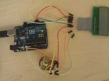
Wiring
- Solder wires to the pins of the LCD (more colors makes the process easier)
- With the pins above the LCD screen connect pins 1 and 5 (from left to right) to an outer terminal (right) on the 10kΩ potentiometer
- Connect pin 2 to the other outer terminal (left) on the potentiometer and pin 3 to the middle terminal of the potentiometer
- Connect a wire from the 5V pin of the Arduino to the left terminal of the potentiometer which should be connected to pin 2 of the LCD, then connect a wire from a GND pin on the Arduino to the right terminal of the potentiometer which should be connected to pins 1 and 5 of the LCD
- Connect pins 4, 6, 7, 8, 9, and 10 of the LCD to Digital pins 12, 11 ,5, 4, 3, and 2 on the Arduino respectively
Run it
- Finally, open the example library in the arduino.exe (File\Examples\LiquidCrystal\HelloWorld) and upload it! Note: the potentiometer adjusts the contrast, and needed to be turned mostly to the left (counterclockwise).
Pin ID
- Register select (RS) pin - pin 4
- Read/Write (R/W) pin - pin 5
- Enable pin - pin 6
- Data Pins (D2-D5) - pins 7, 8, 9, and 10
- Display Contrast pin (Vo) - pin 3
- Power Supply pins (+5V and GND) - pin 2 and pin 1 respectively
- LED Backlight (Bklt+ and Bklt-) - n/a