Section 4.4: Phase 2B - Industrial Locations
< Space Transport and Engineering MethodsIndustrial Locations in General
Industrial scale locations are intended to serve larger and more widespread markets at the most efficient levels of size and specialization. There are two main approaches to building locations at this scale. These are continued self-expansion from previous phases, and new construction on Greenfield Sites (previously unused land} or reconstruction on Greyfield or Brownfield sites. These are respectively outdated and underused sites which have been developed in the past, or previously used for industrial/commercial use and possibly contaminated. A mix of self-expansion and new construction may also be used.
To the extent the construction needs exceed existing surplus production capacity, outside funding for land and other resources may be required. This is because industrial-scale sites tend to be large, and it is hard to acquire land for them in small increments. Once acquired, there is an incentive to put the land to use right away. Because sources of supply and customers are more widespread at this scale, transport capacity becomes more important. Outside market forces also become more important than internal needs of a local community. Since those forces can't be entirely predicted, one way to deal with them is distributing ownership across multiple industries. Work and equipment can then be redistributed as needed when markets shift.
Industrial Scale Habitation
This includes large scale construction which is intended to be occupied by people. Examples include large office buildings, hotels, residential towers, retail complexes, and entertainment venues.
Industrial Scale Transport
This includes large scale transport of energy, discrete and bulk cargo, fluids and gases, people, and data.
Transport to Low Orbit
This type of transport is included here because production, control, and operations for early low orbit transport mostly occurs in moderate environments on Earth. Some of it may be from difficult locations on Earth, and in later phases involve substantial capacity in low orbit, or from farther destinations. They will be discussed in their respective sections later.
*****[Text still to be merged & updated]*****
As part of our overall space development project, we need a way to start putting payloads in orbit and doing activity in space. The choices are to use existing launchers made by other people, build our own, or a mix of the two. For the first choice you would look at the relevant User's Manuals for the existing launchers, and consult with their offices for the launchers that looks suitable. For small hardware mass it is possible to travel as a secondary payload along with a larger primary payload belonging to someone else. That can reduce the launch charges.
For the self-build options we do preliminary designs, then compare to the existing launcher choices. We need to make some design assumptions to start with:
- Payload Mass - We will assume that 20 kg is sufficient mass for a functional hardware item using modern technology. That might need to be changed with a better understanding of payload needs, but we will use it as a starting point. Larger devices can be assembled from several items in orbit, but keeping the item size small lets you use a smaller launch vehicle, and thus lower development cost to start. There is also the possibility to use this as an "express package delivery" service between larger launches on other vehicles, and bring in some revenue.
- Launch Rate - We assume an initial rate of about 1 launch per month, and continuing on a steady basis.
- Production - We assume one or more Advanced Manufacturing type factories, as described on the previous page, are used to build the launcher. This imposes production capabilities on the factory and links the systems. Any materials or components that are not reasonable to make within the factory are bought. The cost of the factory has to be included when deciding which launcher to use.
There are multiple possible ways to launch a small payload to orbit. The conventional approach would be to design a small rocket with two or three stages. Any alternative ideas can be compared to that to see if it has a lower expected development and operating cost.
Small Multistage Rocket
We first consider a conventional rocket. The design process starts with some initial assumptions, from which we can make an estimate of the vehicle size. We then progressively add more detail and do more accurate estimates. This will replace our initial estimate with a series of better ones, and possibly force revising the assumptions. A complete preliminary design considers all the major components and is at the point where you would start the detailed design and final drawings. We will not carry it that far, but intend to show enough of the process to demonstrate how it would be done.
Design Assumptions
- Payload: 20 kg to 250 km orbit. We have to specify an orbit to calculate the mission velocities.
- G-Limit: 10 gravities or 100 m/s2 - This is to keep accelerations and structural loads in the range of existing space hardware designs, and so not force new designs and research for the payloads.
- Exhaust Velocity: 3300 m/s in vacuum - This is typical of a good Hydrocarbon/Oxygen propellant mix.
- All stages are re-used for cost reasons. Hardware mass fractions are assumed to be 14, 15, and 18% for the first to third stages. The upper stages would have higher fractions due to smaller size and increasing heat shielding.
- Launch Site: Equator at 4600 m altitude - This is at Cayambe, Ecuador to take the most advantage of the Earth's rotation and highest starting altitude to reduce drag and mission velocity.
Preliminary Estimate
Conventional rockets are sized by the Rocket Equation, which determines propellant mass ratios. A preliminary estimate of the velocity required can be made from experience. A second estimate will use a trajectory simulation that calculates fuel use, thrust, drag, and acceleration in small time steps.
The ideal velocity to reach a 250 km orbit neglecting losses is found from the total energy of that orbit, which is the sum of kinetic and potential energy. Velocity is 7756 m/s, with an energy of 30.08 MJ/kg, and potential energy is 2.375 MJ/kg. The sum implies a velocity of 8,056 m/s. The various real losses may be estimated at 900 m/s based on experience, giving a total ideal velocity of 8956 m/s. Rotation of the Earth at the Equator is 465 m/s, thus the rocket has to produce a net velocity of 8,491 m/s. If we divide it equally into 3 stages, this gives 2830 m/s per stage. Mass estimates are calculated from top to bottom as follows:
- Payload = 20 kg
- Stage 3 final mass /initial mass = 42.4% - From rocket equation
- Stage 3 hardware fraction = 18% - of entire stage including payload
- Stage 3 initial mass = 20 kg / payload fraction = 20 kg / (final mass - hardware) = 81.9 kg
- Stage 2 m(f)/m(i) = 42.4%
- Stage 2 hardware = 15% x (100-42.4%) = 8.64% - of 2nd stage fuel only
- Stage 2 initial mass = 81.9 kg / (42.4% - 8.64%) = 242.5 kg
- Stage 1 m(f)/m(i) = 42.4%
- Stage 1 hardware = 14% x (100-42.4%) = 8.06% - of 1st stage fuel only
- Stage 1 initial mass = 242.5 kg / (42.4% - 8.06%) = 706 kg
Second Size Estimate
To make a second estimate we need some details of the rocket thrust and drag, and therefore it's size and shape. We assume Oxygen/Methane fuel at 3.6:1 mixture ratio by mass. The chemistry of CH4 + 2O2 = CO2 + 2H2O has a theoretical mass ratio of 4 Oxygen : 1 Methane. By using slightly less Oxygen some of the Methane is left unburned, leaving CO or H2 in the exhaust. This lowers the average molecular weight and increases the exhaust velocity. It also ensures the combustion is not Oxygen rich, which would tend to react with surrounding materials.
- Tank Sizing:
From our preliminary masses above, we can determine tank sizes from the density of the respective fuels: Oxygen = 1140 kg/m3 and Methane = 423 kg/m3:
- From above, all stages have a final mass of 42.4% of initial mass, therefore burn 57.6% of initial mass of fuel. Therefore fuel masses are 406.7, 139.7, and 47.2 kg.
- With a mixture ratio of 3.6:1, the Methane component is 1/4.6 = 21.74% by mass, and Oxygen is the remainder. Thus the Methane mass by stage is 88.4, 30.4, and 10.25 kg, and the Oxygen mass by stage is 318.3, 109.3, and 36.95 kg.
- From the densities we can calculate the respective tank volumes. Allowing 3% extra volume so that there is some pressurizing gas at the top of the tank and fuel margin, we obtain first stage tank volumes of 215 and 288 liters, second stage of 74 and 98.75 liters, and third stage of 24.95 and 33.35 liters for Methane and Oxygen respectively.
- Rocket stage tanks can share a common wall between fuel and oxidizer if they are fully sealed, and usually use an ellipsoidal dome with a 70% height ratio to minimize structural mass. We assume the payload has a density of 1 kg/liter, and thus requires 20 liters volume. For aerodynamic and structural reasons we want to keep the total vehicle height at 10 times the base diameter or less. Each combined stage tank can be modeled as two ellipsoidal domes plus a cylinder. Applying some geometry results in tank diameters of 60, 42, and 30 cm.
- Drag Coefficient:
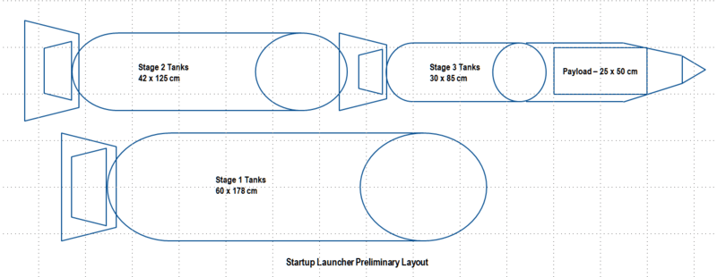
From the tank sizes we can do a preliminary layout of the vehicle. We have to include a forward payload fairing and aft engine sections for each stage to get the total height of the vehicle. For this design we assume an aerospike type engine with platelet injectors for each stage, which gives a total vehicle height of about 6 meters. The layout shown here is not intended as a design drawing. It is a schematic sketch to estimate size and shape of the cylinder and cone sections, from which the drag can be estimated. The layout grid lines are at 25 cm spacing.
At our assumed launch altitude of 4600 m, air density is 0.769 kg/m3, velocity averages 120 m/s in the subsonic region, the rocket length is 6 meters, and the reference viscosity of air is 18.27 x 10⁻⁶ Pa-s. Therefore the Reynolds number, Re, averages 30.3 million, but it will change with altitude and velocity. From reference data as a function of velocity and Re, the skin friction coefficient, Csf, will vary from about 0.0032 at low velocity, to 0.00245 at 120 m/s, to 0.00215 at 240 m/s. This is adjusted by a correction factor based on the shape of the rocket, which in this case is 1.085, and the wetted area to cross section ratio, which is ~8.3/0.283 = 29.3. Thus the total drag will vary from 0.102 to 0.078 to 0.068 at the given speeds, based on cross section area.
Drag coefficients in the transonic and supersonic velocity ranges behaves differently.
If the vehicle had a base area exclusive of the nozzle, we would need to add base drag. In the case of a functioning rocket, the exhaust fills the base and there is no low pressure area to create a net force by pressure difference relative to the front. If the vehicle flies other than directly pointing in the direction of motion, there will be an additional component of drag due to lift, but for this estimate we assume a zero-lift trajectory for simplicity.
- Trajectory:
The launch trajectory cannot be determined by a simple formula or graph, because the thrust, drag, and mass of the vehicle are all varying continuously. Therefore a simulation must be done in small time steps so that the above parameters are nearly constant within each step. If the average values within each step are close to correct, then the total trajectory will be nearly correct. This is too many calculations to do by hand, so a computer program or spreadsheet is used.
The simulation will take as inputs variable vehicle masses and a Trajectory Profile, which is how the vehicle tilts vs time and varies thrust or does staging. The inputs are varied until the desired payload mass and orbit is reached.
Augmented Rocket
An alternative to a conventional rocket is to augment the rocket stages in some way. The extra cost and complexity of these methods has to be compared to any performance and weight improvements they generate. These methods include:
- Ejector Rocket - This is a low grade augmentation by entraining air flow with the rocket exhaust. It increases thrust in the first stage by increasing mass flow.
- Carrier Aircraft
- Balloon Launch
- Jet Boost
- Gas Accelerator