Robotics/Design Basics/Tools and Equipment
< Robotics < Design BasicsYou can't build a robot without at least a few tools. This page will cover some of the tools and equipment that'll be useful.
Mechanical Tools
For building your robot you'll need some tools to form the body.
- Small vise: you'll need this.
- Hammer: A hammer is one of the standard tools you'll need.
- Screwdrivers & Wrenches: their uses are obvious. Two spanners of equal size are required for locknutting.
- Saw: Metal and wood saws. Miter saws can be very handy, but are pretty expensive. A miter box might suffice for many purposes.
- Square, measuring tape, scriber and other marking out tools.
- Vernier calipers: Allow very accurate marking out and measurement. Also can be used to check thread pitch on machine screws without a dedicated pitch gauge.
- Files: especially when working with metal, as rough metal edges are sharp.
- Centre Punch: Essential for accurate drilling of holes in metal to prevent the drill skating over the surface.
- Drill Press: (small table top versions suffice) is very handy for drilling accurate holes. Can also provide the low speeds for drilling large holes in metal, which hand drills cannot do easily.
- Hobby Tool: Useful for many purposes.
- Sharp utility knifes: Mostly used when working with plastics.
- Hot glue guns: handy for quickly mounting parts. Not too strong bound, but useful for many applications.
- Arc Welder: Only useful when working with thick steel on large projects (use a gas welding torch for thin metal;arc welders tend to burn holes right through the workpiece). Aluminium cannot be welded with ordinary welders. (Unless you have a MIG/MAG or TIG welder available)
- Paint stripper/Electric Heat Gun: like a hairdryer on steroids. Useful for bending plastics, also applying heat-shrink tubing to electric cables at low power.
- Safety Goggles: You only get one pair of eyes, and machine tools are potentially dangerous. Safety goggles are essential for using anything other than hand tools.
Electronic Tools
Soldering iron
The soldering iron is a very useful tool for assembling electronic circuits and connecting copper wires together.
For electronic circuits you'll need a light soldering iron (~25W) with a small point (shaped like a pencil point). Especially SMD components require small points (or even better: special SMD soldering points).
Soldering electronic components is done with "soft soldering": with a low temperature (less than 300°C). Usually for electronics the melting point of the solder lays around 238°C. When buying solder choose for a solder wire (60% lead, 40% tin) with non-corrosive flux. (There is also "eutectic solder" - 63% lead, 37% tin, which transitions from liquid to solid immediately, with no plastic state in between.) Take the thinnest wire you can find (<=1mm).
See this page for an in depth explanation of soldering electronic components.
For connecting metal wires you'll need something more powerful (30W-100W) like a soldering pistol, but an ordinary soldering iron would do just as well. Note: not all materials are as good to solder. Copper is easy to solder and has a reasonable strong bond. Aluminum has a weak bond.
For stronger connections it's better to braze instead of soft soldering. Brazing involves higher temperatures (typical between 450°C and 1000°C) and different flux ("Borax") and solder (copper and zinc or silver alloys) it also requires a welding torch instead of a soldering iron.
see this online book for more in depth information on brazing.
If you need even more strength you could use welding. However welding is only used for heavy materials like steel alloys and these are in most cases too heavy to be used in robots (unless you're building a very big or industrial robot). Aluminum can be welded but it isn't as simple as welding steel alloys.
See this site for basic welding information.
Breadboard
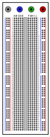
The boards allow you to build a temporary circuit in no time. Especially handy for testing new circuits. Connections are made with either ordinary thin stiff wire with the insulation removed at the ends or with special breadboard wires with stronger tips. Wires with crocodile clamps are needed for hooking up signal generator, oscilloscope, DMM, etc. Larger boards have connectors (typically banana plugs) for the power supply.
There are small breadboards with an adhesive strip at the bottom. These can be mounted on an empty part of a microcontroller board and can be used to build small circuits.
- Note: when you build a sensitive analog circuit on a breadboard, it can behave differently than when it's build as a PCB. This is because of parasitic components: the wires connecting the components on the board act as a combination of a resistor, capacitor and coil (all with very low values). Keep in mind that in some circumstances this can affect the working of a circuit. Usually this is only a problem when working with low amplitudes and/or high frequencies.
Electronic Equipment
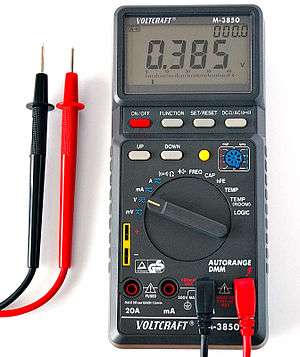
- Multimeter: measures voltage, current & resistance. Many can measure transistor and diode characteristics, frequency and capacity. Some can measure temperature or light intensity.
- Note: measuring voltage and current of a AC source isn't as simple as measuring DC levels. But since robots rarely use AC this would be out of the scope of this text. But if you would require to measure AC levels you should read up on this.
- Oscilloscope: makes a electric signal visible. Very useful when working with more complicated electronic circuits, especially analog signals and data communication. Oscilloscopes exist as stand-alone devices or as add-on modules for PCs. The latter provides extra abilities like spectrum analysing and recording of signals.
- Variable power supplies: power supplies with variable output. Either AC or DC. Either the output voltage or current can be regulated, although most power supplies let you set a max current.
- Signal generators: generates different shapes of signals (sine, square, saw and triangle), with variable frequency (1Hz up to 100MHz) and amplitude.
- Logic probe: pen-like devices that detect logic levels (either TTL or CMOS). Most can detect pulse signals. Very handy when working with digital electronic circuits.
- Frequency meters: measures the frequency of a signal. Can also be used as a pulse counter. Oscilloscopes can be used for measuring frequency, and storage scopes can freeze a waveform onscreen allowing pulses to be manually counted, but frequency meters are a good investment if this needs to be done very often.
- LEDs: An underrated test device for digital circuits. LEDs are far better than voltmeters for digital circuits in some situations, as you can see many input and output values concurrently, without connecting a multitude of voltmeters or constantly checking everything with a logic probe. In particular, they can instantly show the status of several logic signals simultaneously, impossible with a logic probe. Good breadboard building practice also includes an LED for each breadboard to show it is powered up correctly - this can help avoid the potentially frustrating situation of faultfinding a logic circuit that is actually sound, but has an intermittent or noisy power supply. It's also an excellent indicator if a component is short-circuiting at any time during operation, as the LED will likely dim or go out.
Connectors
Insulation Displacement Connectors (IDC)
Assembling parallel ribbon cables from ribbon and the IDC connectors:
Practical tips:
- Note that IDC ribbon cable is usually not provided with multicoloured or ‘rainbow’ insulation, but with single-colour insulation — usually grey or white. However it also has a stripe of coloured ink or paint (red or black) down one side, to guide you with connector orientation. If you need to strip away some of the wires of a multi-way cable to suit the IDC
connectors you’re using, remove them from the side furthest from the ink stripe so it’s still present on the cable.
- It’s usual to fit IDC connectors to the cable so their pin 1 end is on the stripe side of the ribbon. This also
helps guide you when you’re mating the cable connectors with those on the equipment, knowing that the stripe corresponds with pin 1.
- Before clamping an IDC connector to a ribbon cable, make sure that the cable grooves are aligned with the contact jaw tips and that they are also aligned with the scallops moulded into the underside of the clamping strip.
- Make sure too that the connector pin/jaw axis is as close as possible to 90° with respect to the ribbon cable wire axes. If the connector/ribbon angle is not close to 90°, some connections may not be made properly. If the connector is being fitted at the end of a ribbon cable, cutting the end of the ribbon cleanly square first will allow you to use it as a guide.
- Try to squeeze the IDC connector and its clamping strip together as evenly as possible, so they remain as close as possible to parallel with each other during the operation. This too ensures that all joints are made correctly. The easiest way to squeeze them together evenly is by using a small machine vice or a special compound-action clamping tool.
- If an IDC connector has a second cable clamping strip, don’t attempt to fit this as part of the main assembly. Assemble the main parts of the connector first on the ribbon cable, and only then fit the second clamping strip.
- When you are bending the ribbon cable around before fitting the second clamping strip, don’t pull it hard. This may loosen some of the connections inside the IDC connector. Just bend the ribbon around gently — a small amount of slack won’t do any harm, and may in fact protect the IDC connections from strain.
Properly-assembled IDC connector illustration:
http://www1.electusdistribution.com.au/images_uploaded/IDCconnE.pdf
Practical uses:
A common IDC cable in use is an IDC D9 socket to IDC 2 by 5 header socket. This cable is often used to connect a PC serial (RS232) port to a microcontroller development board. On the board there will be a 2 by 5 pin header.
RJ45 network connector
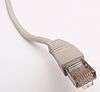
These are the connectors used on UTP network cables. A smaller version (RJ11) is used for telephones. You need a crimping tool to attach the connector to the cable. These connectors are very useful for hooking up different PCB with each other. A good use for RJ45 connectors is for making serial (RS232) programming cables for small embedded systems (many credit card terminals use a DB9 to RJ45 cable to download software from a PC during development). If you are building small embedded controller boards an RJ45 can be a handy connector size to use.