Robotics/Design Basics/Design software
< Robotics < Design BasicsRobotics: Design Basics: Design software
When designing your robot there are plenty of programs to help. Ranging from a simple tool to print wheel encoders, through CAD drawing programs up to mechanical simulation programs.
2D CAD
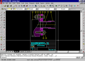
e.g. AutoCAD. This type of software is used to turn a rough sketch into a nice professional drawing. This type of drawing is standardized for readability. (Meaning every different type of line has a particular meaning. Solid lines are visible edges, dashed lines are hidden edges, line-dash-line lines are center lines. Standards also include methods of dimensioning and types of views presented in a drawing.) Of course you're free to use your own standards, but using an industrial standard, such as ANSI or ISO, makes it easier to share your plans with other people around the world. While it may somewhat more tedious to make a drawing using 2D software, the results are generally better than using 3D solid modeling software. Solid modelers still have problems translating 3D models into 2D drawings and adding proper notation to standards.
- GPL CAD software: QCad Wikipedia:QCad
- GPL vector drawing software: Inkscape Wikipedia:Inkscape
Solid Modeling
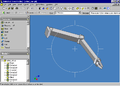
Inventor 5.3 Rotating a part 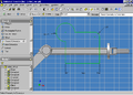
Inventor 5.3 Drawing a Schematic on a part
e.g. SolidWorks or Pro/Engineer Pro/Engineer (Wikipedia:Pro/ENGINEER). A newer way to draw parts and machines. With solid modeling you "build" the parts in 3D, put them together in an assembly and then let the software generate the 2D drawings (sounds harder than it is). The major advantage over 2D CAD programs is you can see the complete part/machine without actually building it in real life. Mistakes are easily found and corrected in the model. These 3D models are not yet completely standardized though there is a standard for digital data. At this time the 2D drawings this software generates do not conform completely to industrial standards. The 2D paper drawing is still the communication tool of preference in industry and clarity of intent is very important. Solid modeling software tend to generate overly complex drawing views with overly simplified dimensioning methods that likely do not correctly convey the fit, form or function of the part or assembly.
Pneumatic & Hydraulic Simulation
Festo has a demo version of both a pneumatic and a hydraulic simulation program. Look for FluidSIM Pneumatiek and FluidSIM Hydraulica. (Pick country; click on industrial automatisation; and use the search field to the right.)
Limitations: Can't save nor print. Most of the didactic material isn't included.
IRAI has a free demonstration version of electric / pneumatic and hydraulic simulation software : AUTOMGEN / AUTOMSIM. Go to Download / AUTOMGEN7.
Schematic Capture & PCB
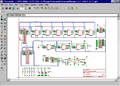
Eagle Schematic capture 
Eagle printed circuit board design
Software to draw electronics schematics and designing Printed Circuit Boards (PCBs). These packages contain software to draw the schematic, libraries with symbols, and software to draw the PCBs (with autorouter).
In no particular order:
- Freeware: Eagle is commonly used by beginners for their projects because a limited version is available for free. The toolset is well integrated and has a large hobbiest user base. However, once you progress beyond basic designs, you need to pay for the full version.
- Open Source: The open-source gEDA Project has produced a mature suite of applications for electronics design, including: a schematic capture program, attribute manager, netlister supporting over 20 netlist formats, analog and digital simulation, PCB layout with autorouter, and Gerber viewer. The project was started in 1997 to write EDA tools useful for personal robotics projects, but as of this writing the tools are also used by hobbiests, students, educators, and professionals for many different design tasks. The suite runs best on Linux and OSX, although Windows ports of some apps have been made.
- Open Source: Kicad, wikipedia: Kicad includes schematic capture and PCB layout
- Open Source: Free PCB is a mature Windows only open source PCB drafting tool.
- IntelligentCad.org has a few links to FPGA and PCB design tools (GPL)
µControllers
Programming Languages
There are many different programming languages available for µControllers:
- Assembly: Every µcontroller can be programmed in Assembly. However the differences between µcontrollers can be huge. Assembly gives you the most power of the µcontroller but this power comes with a price: Hard to learn and (almost)no code reuse.
Assembly code is in essence translated machine code. It provides only the instruction set of the processor: add, subtract, maybe multiply, move data between registers and/or memory, conditional jumps. No loops, complex selection or build in I/O as in C/C++, Basic, Pascal, ...
The disadvantage is that you have to implement everything yourself (lots of work even for the most simple programs).
The advantage is that you have to implement everything yourself (programs can be written extremely efficient both in speed and size).
This language is intended for advanced users and is usually only used as an optimisation for code in tight loops or for pushing the performance of a limited device to the edge of its abilities.
Reasons to learn it:- Teaches you how the computer works on its lowest level.
- Provides high speed code which consumes little memory.
Reasons to avoid it: - Limited use.
- Non-portable.
- very hard to master.
Freeware: AVR
- C: C offers power but is much more portable than Assembly. For most µcontrollers there is a C compiler available. The differences between µcontrollers is smaller here, except for using hardware.
Learning C is much easier than learning Assembly, still C isn't an easy language to learn from scratch. However these days there are very good books available on this subject.- Freeware:GCC Tools for AVR Studio Software
- Basic: For many µcontrollers there are special flavours of Basic available. This is the easiest and fastest way to code µcontrollers, however you'll have to sacrifice some power. Still modern basic compilers can produce very impressive code.
- Limited Freeware/payware:Bascom AVR Very good Basic compiler for AVR. Limited to 4Kb programs. There is also a version available for the 8051 µcontrollers.
- Limited Freeware/payware:XCSB PIC Basic compiler. Lite version. No 32-bit integer and floating point support. (OS/2 WARP, Win95, Win98, Win2K, XP and Linux)
- Forth:
further reading:
- Embedded Systems/Embedded Systems Introduction#Which_Programming_Languages_Will_This_Book_Use?
- Embedded Systems/PIC Programming#Compilers.2C_Assemblers
Programmers
After you've written your program, you need to get it into your µcontroller. If you use C or Basic you'll have to compile it. Then use a programmer to upload the code into the µcontroller. There are several different methods for this last step.
- External programmers: This is a device that's connected to a PC. You'll plug the µcontroller IC, EEPROM or other memory IC in its socket and let the PC upload the code. Afterwards you plug the IC in its circuit and test it. Can be time consuming when updating your program after debugging.
- ISP In System Programming: The board with the µcontroller has a special connector to connect to a PC. Hook up the cable, download code, test and repeat. More modern method. Only disadvantage: it consumes some boardspace. Not all µcontrollers support this.
- Bootloader, also called "self-programming": The CPU accepts a new program through any available connection to a PC (no special connector needed), then programs itself. Not all µcontrollers support this. And you also need some other programming method, to get the initial bootloader programmed in (telling it exactly which connector to watch for a new program, the baud rate, etc.).
Debuggers
Modern µcontrollers have on-chip debug hardware called w:JTAG.
Various tools
See This site for:
- The Motion Applet – Path modeling for the differential steering system of robot locomotion.
- The Encoder Designer – A design tool for encoder wheel patterns. (Wikipedia:Rotary encoder)
- RP1 – A mobile-robot simulator.
- Map Viewer – A Mapping Tool For Mobile Robotics.
And "Experimental Robotics Framework" for rapid prototyping of robotics algorithms.[1]
Further reading
- CAD & Linux has a long list of CAD tools that run under Linux, some of them GPL.
- Linux online: CAD/CAM has a long list of CAD tools that run under Linux, some of them GPL.
- Practical Electronics/PCB Layout has more information on using PCB design software.
- Urbiforge has free downloadable links to Urbi and tutorials on how to use Urbiscript. Urbi is AGPL.