Practical Electronics/Parallel RC
< Practical ElectronicsParallel RC
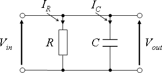
Circuit Impedance


Circuit Response


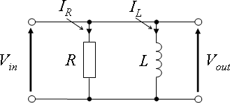
Parallel RL
 \
\
Circuit Impedance


Circuit Response


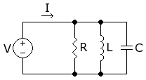
Parallel LC

Circuit Impedance


Circuit response


Parallel RLC
Circuit Impedance


Circuit response


Natural Respond

Forced Respond

Second ordered equation that has two roots
- ω = -α ±

Where


The current of the network is given by
- A eω1 t + B eω2 t
From above
- When , there is only one real root
- ω = -α

- When , there are two real roots
- ω = -α ±

- When , there are two complex roots
- ω = -α ± j


Resonance Response
At resonance, the impedance of the frequency dependent components cancel out . Therefore the net voltage of the circui is zero
and


At Resonance Frequency
- .
- . Current is at its maximum value
Further analyse the circuit
- At ω = 0, Capacitor Opened circuit . Therefore, I = 0 .
- At ω = 00, Inductor Opened circuit . Therefore, I = 0 .
With the values of Current at three ω = 0 , , 00 we have the plot of I versus ω . From the plot
If current is reduced to halved of the value of peak current , this current value is stable over a Frequency Band ω1 - ω2 where ω1 = ωo - Δω, ω2 = ωo + Δω


- In RLC series, it is possible to have a band of frequencies where current is stable, ie. current does not change with frequency . For a wide band of frequencies respond, current must be reduced from it's peak value . The more current is reduced, the wider the bandwidth . Therefore, this network can be used as Tuned Selected Band Pass Filter . If tune either L or C to the resonance frequency . Current is at its maximum value . Then, adjust the value of R to have a value less than the peak current by increasing R to have a desired frequency band .
- If R is increased from R to 2R then the current now is which is stable over a band of frequency
- ω1 - ω2 where
- ω1 = ωo - Δω
- ω2 = ωo + Δω
For value of I < . The circuit respond to Wide Band of frequencies . For value of < I > . The circuit respond to Narrow Band of frequencies
Summary
| Circuit | Symbol | Series | Parallel |
|---|---|---|---|
| RC | 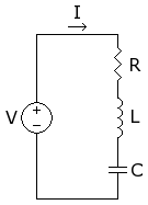 | | |
| Impedance | Z | ||
| Frequency | | | |
| Voltage | V | ||
| Current | I | ||
| Phase Angle | Tan θ = 1/2πf RC f = 1/2π Tan CR t = 2π Tan CR | Tan θ = 1/2πf RC f = 1/2π Tan CR t = 2π Tan CR |


This article is issued from Wikibooks. The text is licensed under Creative Commons - Attribution - Sharealike. Additional terms may apply for the media files.