Practical Electronics/IC/4013
< Practical Electronics < IC| 4013 | |
|---|---|
| Logic Type | Sequential |
| Function Family | Flip-flop |
| Description | Dual D-type flip-flop with asynchronous set-reset |
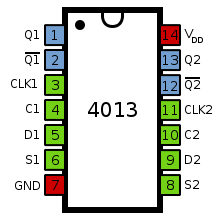
| Pins | 14 |
| Pinout | |
 | |
| Functional Diagram | |
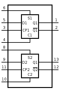 | |
The 4013 contains two independent D-type flip-flops with asynchronous set/reset inputs. Whenever the set or reset pins go high, the appropriate output is expressed immediately on the outputs. When set and reset are low, the output shows the data at the input at the time of the last low-to-high clock transistion. This is then held until the next transistion.
For more information on D-type flip-flops, refer to this module.
Function Tables for a single flip-flop
| Inputs | Outputs | |||||
|---|---|---|---|---|---|---|
| S | R | D | C | Q | Q | |
| H | L | X | X | H | L | |
| L | H | X | X | L | H | |
| H | H | X | X | H | H | |
| Inputs | Outputs | |||||
|---|---|---|---|---|---|---|
| S | R | D | C | Qn+1 | Qn+1 | |
| L | L | L | | L | H | |
| L | L | H | | H | L | |
Further Reading
This article is issued from Wikibooks. The text is licensed under Creative Commons - Attribution - Sharealike. Additional terms may apply for the media files.