Learn Electronics/Resistors
< Learn ElectronicsResistor Circuit Diagram
![]()
Voltage Drop
- Think of a bucket full of water; nothing happens yet, if there is no hole at the bottom of the bucket. The height of the water in the bucket represents the electrical voltage.
- If there is a hole at the bottom of the bucket, then water will flow out of it. That water flow represents electric current flow.
- If the source of the voltage is a battery, then, in time, the battery's voltage will be reduced until there is no voltage left, just as the level of the water in the bucket will get lower and lower until no water is left in the bucket, with zero level.
- If the source of the voltage is the socket in the wall, then the voltage will remain about the same; normally there will be only slight changes of that kind of voltage.
The voltage is the source of the current, and the current has some purpose, it flows through what is called a "load", which may be one or more resistors. No current flows through a resistor or equivalent, unless there is a voltage acrosss the two terminals of the resistor. If there are at least 2 resistors, or equivalent, in series (like a river flowing via 3 points) then the voltage across each resistor is called voltage drop. Think of a river passing via points A, B, and C, where A is highest and C is lowest. There is a difference in the elevations/levels, with B minus A representing a voltage drop, and C minus B being like another voltage drop. The sum of all of the voltage drops in a circuit always equals the supply voltage, such as the battery voltage.
Ohms Law
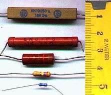
Resistors: Resistors "resist" the flow of electricity, reducing the amount of the current (measured in units called amps). Without a resistor in the circuit the current would be too high, you would ruin parts of the circuit, use up the battery too fast, or even blow the battery. Since resistors are too small to print numbers on them they are labeled with color coded bands that have to be interpreted. Resistors have 3 or 4 colorbands on them, but only the first 3 matter for now. The fourth one is either silver or gold. Silver means it is 10% above or below the value shown by the first 3 bands, while gold means 5% above or below. The first 2 bands represent a one decimal number, the third represents the number of zeros that follow.
Resistors follow Ohm's Law: (V=Voltage, I=Current (in amps), R=Resistance (in ohms))

Ohm's law is important to remember since most electronic components have a maximum and minimum voltage and amp rating: if they're too low it wouldn't work, and if they're too high it will destroy the component. As long as you have at least two values you can solve for the last one.
The Standard EIA Color Code Table per EIA-RS-279 is as follows:
| Colour | 1st band | 2nd band | 3rd band (multiplier) | 4th band (tolerance) Temp. Coefficient |
|---|---|---|---|---|
| Black | 0 | 0 | ×1 | |
| Brown | 1 | 1 | ×10 | |
| Red | 2 | 2 | ×100 (10^2) | |
| Orange | 3 | 3 | ×1000 (10^3) | |
| Yellow | 4 | 4 | ×10000 (10^4) | |
| Green | 5 | 5 | ×100000 (10^5) | |
| Blue | 6 | 6 | ×1000000 (10^6) Highest Multiplier band normally seen | |
| Violet | 7 | 7 | ||
| Gray | 8 | 8 | ||
| White | 9 | 9 | ||
| Gold | ×0.1 ±5% (J) | |||
| Silver | ×0.01 ±10% (K) | |||
| None | ±20% (M) |
A trick to remember is that the decimal number of a color band is equal to the amount of zeros added to the end if it's the third band.
Series & Parallel
(need circuit diagram of resistors in parallel and in series)
Definition of series: In electronics when something is connected in series like a resistor it means that you have resistors that are in a "line". The resistors are connected end to end.
Definition of Parallel: The same wire is connected to one end of all the parts in parallel and another wire is connected to the other end of all the parts in parallel.
(Math for resistors in series and parallel):
Resistors in series: Add their values (in Ohms) to obtain the total resistance of their combination.
Resistors in parallel: The reciprocal (means: one divided by) of the total resistance of the combination of two resistors R1 and R2 is
1/R = 1/R1 + 1/R2, also l/R = 1/R1 + 1/R2 + 1/R3 if there are 3, and so on.
Resistors are very useful in electronic design.
Previous chapter Basics | Next chapter: Capacitors | Go back to Index