Engineering Acoustics/Biomedical Ultrasound
< Engineering AcousticsBiomedical Ultrasound
This chapter of the Engineering Acoustics Wikibook provides a brief overview of biomedical ultrasound applications along with some introductory acoustical analysis for ultrasound beams. As a whole, the field of Biomedical Ultrasound is one that provides a wealth of topics for study involving many base disciplines. As such, this limited entry does not cover all aspects of Biomedical Ultrasound, but instead chooses to focus on providing readers with an introductory understanding, from which additional study of the topic is possible. For readers interested in a more thorough reference on Biomedical Ultrasound the 2007 text by Cobbold [1] is suggested.
Diagnostic Applications
The most well know application of Biomedical Ultrasound is in medical imaging, also known as ultrasonography. For a list of specific applications of ultrasonography refer to the corresponding Wikipedia entry. The following section provides a qualitative description of the acoustical process used to generate and capture sound signals used in producing ultrasound images.
An ultrasound transducer emits a short pulse of high frequency sound. Depending on application the wave frequency ranges between 1 MHz and 15 MHz [2]. As the emitted sound waves propagate they will be partially reflected or scattered by any variation in acoustic impedance, ρc, that is encountered. In the context of to biomedical imaging, this corresponds to anywhere there are density changes in the body: e.g. the connection of bone to muscle, blood cells in blood plasma, small structures in organs, etc. [3].
The behavior of the reflected wave depends largely on the size of the reflective feature and the wavelength of the emitted sound wave. When the wavelength is short relative to the reflective structure reflections will be governed according to the principals of acoustic transmission and reflection with normal or oblique interfaces[4]. When the wavelength is long relative to the structure the principals of acoustic scattering [5] are applicable. The latter condition, which occurs for small reflection sources, sets the requirement for frequencies used in ultrasound imaging. As discussed by Cobbold [6], analysis for a planar wave incident on a spherical reflection source of effective radius a, shows the acoustic intensity of the scattered wave, Is, varies according to:

This relation shows that when wavelength is long relative to a scatter sources effective radius, the scattered energy becomes very small, thus negligible amounts of the incident wave will be reflected back to the transducer. To reliably capture a feature in an ultrasound image the emitted wavelength must be smaller than the features of interest. Other consideration for wavelength are also applicable: due to attenuation of the propagating wave lower frequencies offer greater imaging depth, while higher frequencies (with smaller wavelength) offer increase ability for lateral focusing of the emitted beam (small beam width at focus, see below). [2]. Table 1 gives the correlation between frequency and wavelength in water for several frequencies used in ultrasound imaging (λ = c/f).
| Frequency (MHz) | 1 | 2 | 5 | 8 | 10 | 12 | 15 |
| Wavelength (mm) | 1.50 | 0.75 | 0.30 | 0.19 | 0.15 | 0.13 | 0.10 |
After the wave burst is transmitted the ultrasound transducer can act as a receiver, much like a microphone or hydrophone. Waves reflected off structures and density gradients are returned to the transducer and recorded. The delay time between the transmitted and received signal is correlated to the distance of the reflection source, while the intensity of the received signal is correlated to the reflection sources acoustic impedance and size[3]. In instances where doppler ultrasonography is utilized, the frequency shift between the transmitted and received signals can be correlated to the velocity of the reflection source.
Modern ultrasonography use arrays of small transducers, each of which are individually electronically controlled to achieve an effect know as beamforming. When using this technique, control of the phase relation between array elements results in control over the emitted beam's direction and focal depth [7]. To produce a two-dimensional ultrasound image, the ultrasound beam focal position is swept through a region, and the recorded reflected waves are correlated to the particular focal locations. The exact process by which this general concept is accomplished varies with each ultrasonography instrument. Figure 1 provides a sample 2D image produced by the sweeping of the focal location through a 2D plane.

Clinical and Therapeutic Applications
A number of important clinical and therapeutic applications make use of high intensity, focused ultrasound beams. In many of these applications, the therapeutic effect is achieved due the heat generation associated with dissipation of the high intensity acoustic beam. In some applications, such as lithotripsy the therapeutic effect is obtained from acoustic non-linearity, causing wave deformation and shock wave formation. This effect is discussed in more detail in a section to follow.
Provided below is a partial list of Therapeutic applications of ultrasound:
- Ultrasound is sometimes used to clean teeth in [w:dental_hygienist|dental hygenist]].
- Focused ultrasound may be used to generate highly localized heating to treat cysts and tumors (benign or malignant). This is known as Focused Ultrasound Surgery (FUS) or High Intensity Focused Ultrasound (HIFU). These procedures generally use lower frequencies than medical diagnostic ultrasound (from 250 kHz to 2000 kHz), but significantly higher energies.
- Focused ultrasound may be used to break up kidney stones by lithotripsy.
- Ultrasound may be used for cataract treatment by Phacoemulsification.
- Additional physiological effects of low-intensity ultrasound have recently been discovered, such as the ability to stimulate bone-growth and the potential to disrupt the blood-brain barrier for drug delivery.
Acoustic Properties of Ultrasound Beams
As a first approximation, an ultrasound beam can be considered as resulting from flat circular piston oscillating on an infinite baffle. In practice, such a system would lead to relatively high diffusion of the sound beam, severe side lobes, and an inability to choose a focal length of the acoustic energy. In current biomedical applications the use of phased arrays is a common approach stemming from the more general field know as beamforming. Despite the limitations of planar transducers, their relatively simple analysis serves well to illustrate the basic properties of any formed beam and the challenges of designing more advanced systems.
The analytical approach utilized for the simple cylindrical transducer appears in many acoustics reference Texts, such as those by Pierce[8], Kinsler et al.[9] and Cheeke[10]. The sound field solution is obtained by first considering the sound emitted by the harmonic motion of a single point source (small sphere) vibrating in free space. The resulting sound pressure field from this point source is:


Where P(r) is the harmonic pressure amplitude at the radial distance r, ρo is the fluid density, co is the fluid sound speed, Uo is the maximum velocity of the spherical source, a is the sphere radius, and k = 2πf/co is the wave number. In the preceding equations, i = -11/2, which incorporates both amplitude an phase into the harmonic pressure variable.
To apply this result to the ultrasound transducer as a cylindrical radiator, each differential section of the cylinder surface can be considered as a separate spherical source. The resulting sound field from this approximation is the integral sum of each spherical source. In general the resulting equation cannot be analytically integrated; however, when considering regions of the field for r >> a, where a is now the cylinder radius, a simple result is found. Forgoing the full derivation (for reference see Kinsler [9] or Cheeke [10]), the equations for the produced sound field and acoustic intensity are:


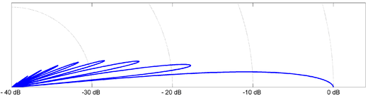
where H(θ) is the directivity function, J1 is the Bessel Function of the first kind, and I(r) is the acoustic intensity in W/m2. Physically the directivity function represents the pressure amplitude for beam angles not parallel to the cylinder axis. It is worthwhile to note that roots of the Bessel function produce certain beam angles with zero amplitude; the regions between these angles are known as side lobes, with the on axis component know as the main lobe. Physically, lobes result from the phase interaction of waves originating from different parts of the cylindrical transducer, and are in some ways analogous to pressure nodes in simple harmonic waves.
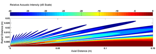
To illustrate the phenomena of side lobes in ultrasound beams, the resulting directivity function and acoustic intensity is calculated for a 1 MHz beam transmitted into water using a 1 cm radius transducer. Figure 2 plots the Directivity function, while Figure 3 plots the acoustic intensity relative to the intensity at the transducer surface.
For the purposes of diagnostic and therapeutic ultrasound the presence of side lobes is an undesirable effect. In diagnostic imaging wave reflection originating from the side lobes can be misinterpreted as reflections from the main beam, and act to reduce the resulting image quality. In therapeutic applications, side lobes represent energy dissipation on regions not intended to be effected. To reduce the effects of side lobes, ultrasound devices use transducer designs based on beamforming theory, making the analysis substantially more complicated than the simple cylindrical transducer discussed. One technique to reduce side lobes is the use of a phased array to focus the main at a particular depth, thus reducing the relative magnitude of side lobes. Another technique known as acoustic shadowing reduces side lobes by emitting lower amplitude waves near the edge of the transducer. As will be discussed in a proceeding section, an emerging technique to enhance focusing and reduce side lobes is the purposeful consideration of nonlinear acoustic effects in ultrasound beams [1][11].
Nonlinear Acoustics in Biomedical Ultrasound
In many fields related to application of acoustic theory, the assumption of linear wave propagation is sufficient. In Biomedical ultrasound however, the propagation of sound waves is often accompanied by progressive wave distortion resulting from nonlinear, finite amplitude, effects. The nonlinear effect of most interest in many diagnostic applications is the generations of harmonics in the ultrasound beam. As a primer to this section, a review of the acoustic parameter of nonlinearity, and harmonic generation is suggested.
Nonlinearities relevant to Biomedical Ultrasound are relatively weak, making their effects on the propagating acoustic wave cumulative with distance. For appreciable harmonic generation to occur four conditions should be met:
- Sufficient pressure and velocity amplitude. The waves emitted for almost all applications of biomedical ultrasound meet this requirement[12].
- Sufficient propagation distance with near planar wave conditions. For directional beams, such as those used in ultrasonography, this conditions is approximately met within the Rayleigh Distance, x = 1/2 ka2, on the main lobe[13]. Furthermore, harmonic generation is proportional to the number of wavelengths propagated and not the absolute distance. The ultrasonic frequencies utilized have very short wavelengths, for example, a 10 MHz wave must propagate over 500 wavelengths for a focal depth of 10 cm.
- Sufficient value of the parameter of nonlinearity, B/A. For the same acoustic intensity, a material with a higher value of B/A will produce harmonics more quickly. The value of B/A in water is ten times that in air, and B/A for some biological tissues can be double that of water.
- Low acoustic absorption. In many tissues with high values for B/A there are also high values for acoustic absorption. As the extent of wave dissipation increases with frequency, generated harmonics are absorbed more readily than the fundamental frequency. This effect reduces the influence of B/A in biological tissues relative to that in low-loss fluids [12].
Reviewing these conditions it can be seen that in many circumstances, harmonic generation will be appreciable in biomedical ultrasound. Two developing applications that make use of this harmonic generation are:
- Use of harmonic content in recorded ultrasonography signals. As acoustic intensity and propagation distance is highest on the main lobe, harmonic generation occurs most significantly on the main lobe, and is smaller on side lobes. As a result, the beam pattern produced by 2nd harmonics is more directional than the beam produced by the fundamental frequency. This allows for potential improvement in the resulting image [11].
- The analysis of harmonic profiles for tissue characterization using the B/A parameter. Referring to The Acoustic Parameter of Nonlinearity, values of B/A vary for tissues that have otherwise similar acoustic impedance. As a result, harmonic content in ultrasound waves has the potential to produce images correlated to the B/A parameter of tissues. Practical realization of this concept is an area in development, as current imaging methods are unable to utilize this potential[12].
External Links
Medical Ultrasonic Transducers
References
- 1 2 Cobbold, R. S. C. 2007. Foundations of Biomedical Ultrasound. Nonlinear Ultrasonics. Oxford University Press.
- 1 2 Kremkau, F. W. 2002. Diagnostic Ultrasound : Principles and Instruments. Philadelphia, W.B. Saunders
- 1 2 Wikipedia, 2010. "Medical Ultrasonography”
- ↑ Kinsler, L. E., Frey, A. R., Coppens, A. B., Sanders, J. V. 2000. Reflection and Transmission. In Fundamentals of Acoustics. New York, Wiley.
- ↑ Pierce, A. D. 1989. Scattering and Diffraction. In Acoustics : An Introduction to its Physical Principles and Applications. Woodbury, N.Y., Acoustical Society of America.
- ↑ Cobbold, R. S. C. 2007. Scattering of Ultrasound. In Foundations of Biomedical Ultrasound. Nonlinear Ultrasonics. Oxford University Press.
- ↑ Cobbold, R. S. C. 2007. Ultrasound Imaging Arrays. In Foundations of Biomedical Ultrasound. Nonlinear Ultrasonics. Oxford University Press.
- ↑ Pierce, A. D. 1989. Radiation from Sources Near and on Solid Surfaces. In Acoustics : An Introduction to its Physical Principles and Applications. Woodbury, N.Y., Acoustical Society of America.
- 1 2 Kinsler, L. E., Frey, A. R., Coppens, A. B., Sanders, J. V. 2000.Radiation and Reception of Acoustic Waves. In Fundamentals of Acoustics. New York, Wiley.
- 1 2 Cheeke, J. D. N. 2002. Finite Beams, Radiation, Diffraction, and Scattering. In Fundamentals and Applications of Ultrasonic Waves. Boca Raton, CRC Press.
- 1 2 Duck, F. A. 2002. "Nonlinear Acoustics in Diagnostic Ultrasound." Ultrasound in Medicine & Biology 28(1).
- 1 2 3 Duck, F. 2010. Tissue non-linearity. Proceedings of the Institution of Mechanical Engineers, Part H: Journal of Engineering in Medicine 224(2).
- ↑ Hamilton, M. F., Blackstock, D. T. 2008. Sound Beams. In Nonlinear Acoustics. Melville, NY, Acoustical Society of America.