Electronics/Resistors
< ElectronicsElectronics | Foreword | Basic Electronics | Complex Electronics | Electricity | Machines | History of Electronics | Appendix | edit
Resistor
A resistor is a block or material that limits the flow of current. The greater the resistance, the lower the current will be, assuming the same voltage imposed on the resistor. The hydraulic analogy of a resistor would be the pipe with water flowing through it. The wider the diameter of a pipe, the higher the water flow through the pipe, assuming the same pressure difference on the terminals of a pipe.
Resistor's Symbol
Resistors have two leads (points of contact) to which the resistor can be connected to an electrical circuit. A symbol for a resistor used in electrical circuit diagrams is shown below.
The endpoints at the left and right sides of the symbol indicate the points of contact for the resistor. The ratio of the voltage to current will always be positive, since a higher voltage on one side of a resistor is a positive voltage, and a current will flow from the positive side to the negative side, resulting in a positive current. If the voltage is reversed, the current is reversed, leading again to a positive resistance.
Resistance
Resistance is a characteristic of Resistor indicates the measurement of current opposition . Resistance has a symbol R measured in Ohm (Ω) . The ratio of voltage to current is referred to as Ohm's Law, and is one of the most basic laws that govern electronics.

An ohm is the amount of resistance which passes one ampere of current when a one volt potential is placed across it. (The ohm is actually defined as the resistance which dissipates one watt of power when one ampere of current is passed through it.)

Resistance can vary from very small to very large. A superconductor has zero resistance, while something like the input to an op-amp can have a resistance near 1012 Ω, and even higher resistances are possible.
Resistance and Temperature
For most materials, resistance increases with increasing Temperature
- For Conductor .
- For Semi Conductor .


Resistance and Electric Power Loss
Resistance converts Electrical Energy into Heat this causes Electric Energy Loss.

NOTE : Resistors which dissipate large amounts of power are cooled so that they are not destroyed, typically with finned heatsinks.
If Electric Energy Supply is Pv and Electric Energy Loss is Pr Then, Electric Energy Delivered is


The ratio of Electric Energy Delivered over Electric Energy Supplied indicates the Efficiency of Electric Power Supply


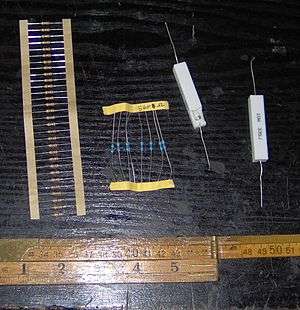
Resistor's Labeling (See also Identification)
A manufactured resistor is usually labeled with the nominal value (value to be manufactured to) and sometimes a tolerance. Rectangular resistors will usually contain numbers that indicate a resistance and a multiplier. If there are three or four numbers on the resistor, the first numbers are a resistance value, and the last number refers to the number of zeroes in the multiplier. If there is an R in the value, the R takes the place of the decimal point.
- Examples
- 2003 means 200×103 = 200kΩ
- 600 means 60×100 = 60Ω
- 2R5 means 2.5Ω
- R01 means 0.01Ω
Cylindrical resistors (axial) usually have colored bands that indicate a number and a multiplier. Resistance bands are next to each other, with a tolerance band slightly farther away from the resistance bands. Starting from the resistance band side of the resistor, each colour represents a number in the same fashion as the number system shown above.
Colour System
Black Brown Red Orange Yellow Green Blue Violet Grey White 0 1 2 3 4 5 6 7 8 9
Clue : B.B.ROY of Great Britain was a Very Good Worker. Additional Colours: A gold band in the multiplier position means 0.1, but means a 5% tolerance in the tolerance position. A silver band in the multiplier position means 0.01, but means 10% in the tolerance position.
Resistor's Construction
The resistance R of a component is dependent on its physical dimension and can be calculated using:

where
- ρ is the electrical resistivity (resistance to electricity) of the material,
- L is the length of the material
- A is the cross-sectional area of the material.
If you increase ρ or L you increase the resistance of the material, but if you increase A you decrease the resistance of the material.
Resistivity of the Material
Every material has its own resistivity, depending on its physical makeup. Most metals are conductors and have very low resistivity; whereas, insulators such as rubber, wood, and air all have very high resistivity. The inverse of resistivity is conductivity, which is measured in units of Siemens/metre (S/m) or, equivalently. mhos/metre.
In the following chart, it is not immediately obvious how the unit ohm-meter is selected. Considering a solid block of the material to be tested, one can readily see that the resistance of the block will decrease as its cross-sectional area increases (thus widening the conceptual "pipe"), and will increase as the length of the block increases (lengthening the "pipe"). Given a fixed length, the resistance will increase as the cross-sectional area decreases; the resistance, multiplied by the area, will be a constant. If the cross-sectional area is held constant, as the length is increased, the resistance increases in proportion, so the resistance divided by the length is similarly a constant. Thus the bulk resistance of a material is typically measured in ohm meters squared per meter, which simplifies to ohm - meter (Ω-m).
Conductors Ω-m (Ohm-meter) Silver 1.59×10⁻⁸ Copper 1.72×10⁻⁸ Gold 2.44×10⁻⁸ Aluminum 2.83×10⁻⁸ Tungsten 5.6×10⁻⁸ Iron 10×10-8 Platinum 11×10-8 Lead 22×10-8 Nichrome 1.50×10⁻⁶ (A nickel-chromium alloy commonly used in heating elements) Graphite ~10-6 Carbon 3.5×10⁻⁵ Semiconductors Pure Germanium 0.6 Pure Silicon 640 Common purified water ~103 Ultra-pure water ~105 Pure Gallium Arsenide ~106 Insulators Diamond ~1010 Glass 1010 to 1014 Mica 9×10¹³ Rubber 1013 to 1016 Organic polymers ~1014 Sulfur ~1015 Quartz (fused) 5 to 75×1016 Air very high
Silver, copper, gold, and aluminum are popular materials for wires, due to low resistivity. Silicon and germanium are used as semiconductors. Glass, rubber, quartz crystal, and air are popular dielectrics, due to high resistivity.
Many materials, such as air, have a non-linear resistance curve. Normal undisturbed air has a high resistance, but air with a high enough voltage applied will become ionized and conduct very easily.
The resistivity of a material also depends on its temperature. Normally, the hotter an object is, the more resistance it has. At high temperatures, the resistance is proportional to the absolute temperature. At low temperatures, the formula is more complicated, and what counts as a high or low temperature depends on what the resistor is made from. In some materials the resistivity drops to zero below a certain temperature. This is known as superconductivity, and has many useful applications.
(Some materials, such as silicon, have less resistance at higher temperatures.)
For all resistors, the change in resistance for a small increase in temperature is directly proportional to the change in temperature.
Current passing through a resistor will warm it up. Many components have heat sinks to dissipate that heat. The heatsink keeps the component from melting or setting something on fire.
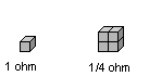
Length
The length of an object is directly proportional to its resistance. As shown in the diagram below, 1 unit cubed of material has 1 ohm of resistance. However, when 4 units are stacked lengthwise and a connection is made to the front and back sides respectively, the total resistance is 4 ohms. This is because the length of the unit is 4, whereas the cross-sectional area remains 1. However, if you were to make connections on the sides, the exact opposite would be true: the cross-sectional area would be 4 and the length 1, resulting in 0.25 ohms total resistance.

Cross-Sectional Area
Increasing area is the same as having resistors in parallel, so as you increase the area you add more paths for current to take.
The resistance of a material is inversely proportional to its cross-sectional area. This is shown in the diagram below, where 1 unit cubed has one ohm of resistance. However, if 4 units cubed are stacked on top of each other in the fashion such that there is 4 units squared of cross-sectional area, and the electrical connections are made to the front and back such that the connections are on the largest sides, the resultant resistance would be 0.25 ohms.
Additional note: There are two reasons why a small cross-sectional area tends to raise resistance. One is that the electrons, all having the same negative charge, repel each other. Thus there is resistance to many being forced into a small space. The other reason is that they collide, causing "scattering," and therefore they are diverted from their original directions. (More discussion is on page 27 of "Industrial Electronics," by D. J. Shanefield, Noyes Publications, Boston, 2001.)
Example
For instance, if you wanted to calculate the resistance of a 1 cm high, 1 cm wide, 5 cm deep block of copper, as shown in the diagram below:
![]()
You would first need to decide how it's oriented. Suppose you want to use it from front to back (lengthwise), like a piece of wire, with electrical contacts on the front and rear faces. Next you need to find the length, L. As shown, it is 5 cm long (0.05 m). Then, we look up the resistivity of copper on the table, 1.6×10⁻⁸ Ω-meters. Lastly, we calculate the cross-sectional area of the conductor, which is 1 cm × 1 cm = 1 cm2 (0.0001 m2). Then, we put it all in the formula, converting cm to m:

units m2 cancel:

Which, after evaluating, gives you a final value of 8.0×10⁻⁶ Ω, or 8 microohms, a very small resistance. The method shown above included the units to demonstrate how the units cancel out, but the calculation will work as long as you use consistent units.
- Internet Hint: Google calculator can do calculations like this for you, automatically converting units. This example can be calculated with this link:
Properties of the material
- Wirewound: Used for power resistors, since the power per volume ratio is highest. These usually have the lowest noise.
- Carbon Film: These are easy to produce, but usually have lots of noise because of the properties of the material.
- Metal Film: These resistors have thermal and voltage noise attributes that are between carbon and wirewound.
- Ceramic: Useful for high frequency applications.
Resistor Connection
Resistors in Series
Resistors in series are equivalent to having one long resistor. If the properties of two resistors are equivalent, except the length, the final resistance will be the sum of the two construction methods:

This means that the resistors add when in series.

- Christmas tree lights are usually connected in series, with the unfortunate effect that if one light blows, the others will all go out (This happens because the circuit is not complete, if a circuit is not complete then the current cannot flow, hence the light bulbs all go out). However, most modern Christmas light strings have built in shunt resistors in parallel to the bulb, so that current will flow past the blown light bulb.
Resistors in Parallel
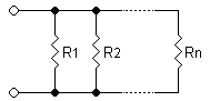
In a parallel circuit, current is divided among multiple paths. This means that two resistors in parallel have a lower equivalent resistance than either of the parallel resistors, since both resistors allow current to pass. Two resistors in parallel will be equivalent to a resistor that is twice as wide:

Since conductances (the inverse of resistance) add in parallel, you get the following equation:

For example, two 4 Ω resistors in parallel have an equivalent resistance of only 2 Ω.
To simplify mathematical equations, resistances in parallel can be represented with two vertical lines "||" (as in geometry). For two resistors the parallel formula simplifies to:

Combinations of series and parallel
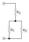
Resistors in parallel are evaluated as if in a mathematical set of "parentheses." The most basic group of resistors in parallel is evaluated first, then the group in series with the new equivalent resistor, then the next group of resistors in parallel, and so on. For example, the above portion would be evaluated as follows:

Resistor variations
- Variable Resistor or Potentiometer
- Variable resistors are tunable, meaning you can turn a dial or slide a contact and change the resistance. They are used as knobs to control the volume of a stereo, or as a dimmer for a lamp. The term Potentiometer is often abbreviated as 'pot'. It is constructed like a resistor, but has a sliding tap contact. Potentiometers are used as Voltage Dividers. It is rare to find a variable resistor with only two leads. Most are potentiometers with three leads, even if one is not connected to anything.
- Rheostat
- A variation of the potentiostat with a high current rating, which is used to control the amount of power going through a load, such as a motor.
- Thermistor
- Temperature-sensitive resistor, in which the resistance decreases as the temperature rises. They are used in fire alarms, so if things get too hot the current rises and trips a switch that sounds an alarm.
- LDR (Light Dependent Resistor) or Photoresistor
- A resistor which changes values depending on the amount of light shining on its surface. The resistance decreases as the amount of light increases. They are used in street lamps, so when it gets dark the current decreases and turns on the street lamp.
Applications
- Voltage division / Attenuation: Sometimes a voltage will be too large to measure, so a means to linearly reduce the voltage is required. Placing two resistors in series to ground will provide a point in the middle to tap. Resistor RA is placed between the input voltage and the output node, and the resistor RB is placed between the output node and ground. This creates a voltage divider to lessen the output voltage. Typically, the resistors are near the value of ~10kΩ. The Thevenin model of the circuit gives an output resistance ROUT = RA||RB. A larger output resistance will more likely be affected by the input resistance of the measuring circuit (this is a desired effect in the transistor biasing circuits). Placement of the voltage divider should be close to the measuring circuit, to minimize noise (in this arrangement, it will be also lessened Rb/(Ra + Rb) times). The output voltage of the voltage divider is

- Pull-up / Pull-down: If there is nothing to drive a signal node, the node will be left "floating" (for example, such a situation occurs at the trigger input of a car alarm system when the driver has switched off the internal lamp). This may lead to unintended values being measured, or causing side-effects when the voltage is propagated down the remainder of the circuit. To prevent this, a relatively high value resistor (usually ~10kΩ to ~1MΩ) is placed between the node and ground (pull-down) or a high voltage (pull-up) to bring the voltage of the "floating" node near to the voltage it is being pulled. A resistive voltage divider is another example where the upper resistor "pulls" the output point up toward the input voltage while the lower resistor "pulls" the output point toward the ground. This idea is evolved in the circuit of a resistive voltage summer (for example, the resistors R1 and R2 of an op-amp inverting amplifier) supplied by two voltages (VIN and -VOUT) having opposite polarities. The two voltage sources "pull" the output point in opposite directions; as a result, if R2/R1 = -VOUT/VIN, the point becomes a virtual ground. Placement of a pull-up or pull-down resistor does not have a significant effect on the performance of the circuit, if they have high resistances.
- Current limiting / Isolation: In order to protect circuits from conditions that may cause too much current in a device, a current limiting resistor is inserted in the middle of the circuit. A digital input to a microcontroller may benefit from a current limiting resistor. The inputs to modern microcontrollers have protection circuitry built in that will protect the input from an overvoltage condition, provided that the current is small enough. For instance, a common microcontroller will be capable of withstanding 20mA. If there are 12V nets on a circuit board, or in a system, the digital input will benefit from a 350Ω resistor (refer to calculation below). Usually a slightly larger resistance is used in practice, but too large of a resistor will cause noise, and may prevent the input from being able to read the voltage. It is good practice to place the resistor as close as possible to the microcontroller input, so that an accidental short on the board will mean that the microcontroller input is likely still protected.

- Line termination / Impedance matching: The properties of an electric wave propagating through a conductor (such as a wire) create a reflection, which can be viewed as unwanted noise. A reflection can be eliminated by maximizing the power transfer between the conductor and the termination resistor. By matching the resistance (more importantly the impedance ), the wave will not cause a reflection. The voltage of the echo V_r is calculated below in reference to the original signal V_o as a function of the conductor impedance Z_C and the terminator impedance Z_T. As the name implies, the termination resistor goes at the end of the conductor.

- Current sensing: Measurement of a current cannot be done directly. There are three major ways to measure a current: a resistor, a hall sensor, and an inductor. The hall sensor and inductor use a property of the magnetic field to sense the current through a nearby conductor. According to Ohm's law, if a current I flows through a resistor R, a voltage V = R.I appears across the resistor. Therefore, the resistor can act as a passive current-to-voltage converter. In this arrangement, the resistor should have a very low value (sometimes on the order of ~0.01Ω), so it does not affect the current flow or heat up; however, a smaller value has a lower voltage to read, which means more noise may be introduced. This contradiction is solved in the circuit of an active current-to-voltage converter where the resistor may have a significant resistance as an op-amp compensates the "undesired" voltage drop across it (unfortunately, this remedy may be applied only in low-current measurements). The current sense resistor should be placed as close as possible to where the measurement occurs, in order not to disturb the circuit.
- Filtering: Filtering is discussed later, after an introduction to capacitors and inductors. Filters are best placed close to where measurement takes place.
Specifications
Resistors are available as pre-fabricated, real-world components. The behavior of such components deviates from an ideal resistor in certain ways. Therefore, real-world resistors are not only specified by their resistance, but also by other parameters. In order to select a manufactured resistance, the entire range of specifications should be considered. Usually, exact values do not need to be known, but ranges should be determined.
Nominal Resistance
The nominal resistance is the resistance that can be expected when ordering a resistor. Finding a range for the resistance is necessary, especially when operating on signals. Resistors do not come in all of the values that will be necessary. Sometimes resistor values can be manipulated by shaving off parts of a resistor (in industrial environments this is sometimes done with a LASER to adjust a circuit), or by combining several resistors in series and parallel.
Available resistor values typically come with a resistance value from a so called resistor series. Resistor series are sets of standard, predefined resistance values. The values are actually made up from a geometric sequence within each decade. In every decade there are supposed to be resistance values, with a constant step factor. The standard resistor values within a decade are derived by using the step factor


![{\displaystyle i={\sqrt[{n}]{10}};n=6,12,24,48}](../I/m/733c32c906ec24627c4ebac7b52f828cd15d8c8a.svg)
rounded to a two digit precision. Resistor series are named E, according to the used value of in the above formula.
 n Values/Decade  Step factor i  Series
----------------------------------------
        6             1.47         E6
       12             1.21         E12
       24             1.10         E24
       48             1.05         E48
For example, in the E12 series for , the resistance steps in a decade are, after rounding the following 12 values:

1.00, 1.20, 1.50, 1.80, 2.20, 2.70,
3.30, 3.90, 4.70, 5.60, 6.80, and 8.20
and actually available resistors from the E12 series are for example resistors with a nominal value of 120Ω or 4.7kΩ.
Tolerances
A manufactured resistor has a certain tolerance to which the resistance may differ from the nominal value. For example, a 2kΩ resistor may have a tolerance of ±5%, leaving a resistor with a value between 1.9kΩ and 2.1kΩ (i.e. 2kΩ±100Ω). The tolerance must be accounted for when designing circuits. A circuit with an absolute voltage of 5V±0.0V in a voltage divider network with two resistors of 2kΩ±5% will have a resultant voltage of 5V±10% (i.e. 5V±0.1V). The final resistor tolerances are found by taking the derivative of the resistor values, and plugging the absolute deviations into the resulting equation.
The above mentioned E-series which are used to provide standardized nominal resistance values, are also coupled to standardized nominal tolerances. The fewer steps within a decade there are, the larger the allowed tolerance of a resistor from such a series is. More precises resistors, outside of the mentioned E-series are also available, e.g. for high-precision measurement equipment. Common tolerances, colors and key characters used to identify them are for example:
 Series  Values/Decade  Tolerance  Color Code  Character Code
--------------------------------------------------------------
   E6          6          ±20%       [none]        [none]
   E12        12          ±10%       silver          K
   E24        24           ±5%       gold            J
   E48        48           ±2%       red             G
    -         -            ±1%       brown           F
    -         -            ±0.5%       -             D
    -         -            ±0.25%      -             C
    -         -            ±0.1%       -             B
Resistor manufacturers can benefit from this standardization. They manufacture resistors first, and afterwards they measure them. If a resistor does not meet the nominal value within the defined tolerance of one E-series, it might still fit into a lower series, and doesn't have to be thrown away, but can be sold as being compliant to that lower E-series standard. Although typically at a lower price.
Series: Resistors that combine in series add the nominal tolerances together.
- Derivation:

- Example: For two resistors in series RA = 1.5kΩ±130Ω and RB = 500Ω±25Ω, the tolerance is 130Ω + 25Ω, resulting in a final resistor value RT = 2kΩ±155Ω.
Parallel: Resistors that combine in parallel have a combined tolerance that is slightly more complex.
- Derivation:

- Example: For two resistors in parallel RA = 1.5kΩ±130Ω and RB = 500Ω±25Ω.
Power Rating
Because the purpose of a resistor is to dissipate power in the form of heat, the resistor has a rating (in watts) at which the resistor can continue to dissipate before the temperature overwhelms the resistor and causes it to overheat. When a resistor overheats, the material begins to melt away, which will cause the resistance to increase (usually), until the resistor breaks.
Operating Temperature
Related to power rating, the operating temperature is the temperature that the resistor can continue to operate before being destroyed.
Maximum Voltage
In order to avoid sparkovers or material breakdown a certain maximum voltage over a resistor must not be exceeded. The maximum voltage is part of a resistor's specification, and typically a function of the resistor's physical length, distance of the leads, material and coating.
For example, a resistor with a maximum operating voltage of 1kV can have a length in the area of 2", while a 0.3" resistor can operate under up to several tens of volts, probably up to a hundred volts. When working with dangerous voltages it is essential to check the actual specification of a resistor, instead of only trusting it because of the length.
Temperature Coefficient
This parameter refers to the constant in which the resistance changes per degree Celsius (units in C-1). The change in temperature is not linear over the entire range of temperatures, but can usually be thought of as linear around a certain range (usually around room temperature). However, the resistance should be characterized over a large range if the resistor is to be used as a thermistor in those ranges. The simplified linearized formula for the affect on temperature to a resistor is expressed in an equation:
![{\displaystyle R=R_{0}[1+\alpha (T-T_{0})]}](../I/m/f3e8e265bc52162bc978d948bf55721b587f5797.svg)
Capacity and Inductance
Real world resistors not only show the physical property of resistance, but also have a certain capacity and inductance. These properties start to become important, if a resistor is used in some high frequency circuitry. Wire wound resistors, for example, show an inductance which typically make them unusable above 1kHz.
Packaging
Resistors can be packaged in any way possible, but are divided into surface mount, through hole, soldering tag and a few more forms. Surface mount is connected to the same side that the resistor is on. Through hole resistors have leads (wires) that typically go through the circuit board and are soldered to the board on the side opposite the resistor, hence the name. Resistors with leads are also used in point-to-point circuits without circuit boards. Soldering tag resistors have lugs to solder wires or high current connectors onto.
Usual packages for surface mount resistors are rectangular, referenced by a length and a width in mils (thousands of an inch). For instance, an 0805 resistor is a rectangle with length .08" x .05", with contacts (metal that connects to the resistor) on either side. Typical through hole resistors are cylindrical, referenced either by the length (such as 0.300") or by a typical power rating that is common to the length (a 1/4W resistor is typically 0.300"). This length does not include the length of the leads.
Related Wikimedia resources
Wikibooks
- Circuit Idea: Passive voltage-to-current converter shows how the bare resistor can act as a simple voltage-to-current converter.
Wikipedia
- Voltage-to-current converter builds consecutively the passive and active versions of the voltage-to-current converter.
- Current-to-voltage converter is dedicated to the passive and active versions of the inverse current-to-voltage converter.
Further Readings
- Resistors in Series and Parallel: Electronics for Beginners