Electronics/Flip Flops
< ElectronicsFlip Flop
A flip-flop is a device very like a latch in that it is a bistable multivibrator, having two states and a feedback path that allows it to store a bit of information. The difference between a latch and a flip-flop is that a latch is asynchronous, and the outputs can change as soon as the inputs do (or at least after a small propagation delay). A flip-flop, on the other hand, is edge-triggered and only changes state when a control signal goes from high to low or low to high. This distinction is relatively recent and is not formal, with many authorities still referring to flip-flops as latches and vice versa, but it is a helpful distinction to make for the sake of clarity.
There are several different types of flip-flop each with its own uses and peculiarities. The four main types of flip-flop are : SR, JK, D, and T.
SR Flip Flop
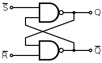
An SR latch (Set/Reset) is an asynchronous device: it works independently of control signals and relies only on the state of the S and R inputs. In the image we can see that an SR flip-flop can be created with two NOR gates that have a cross-feedback loop. SR latches can also be made from NAND gates, but the inputs are swapped and negated. In this case, it is sometimes called an SR latch.
An SR (Set/Reset) flip-flop is perhaps the simplest flip-flop, and is very similar to the SR latch, other than for the fact that it only transitions on clock edges. While as theoretically valid as any flip-flop, synchronous edge-triggered SR flip-flops are extremely uncommon because they retain the illegal state when both S and R are asserted. Generally when people refer to SR flip-flops, they mean SR latches.
.svg.png)
_Flip-flop.svg.png)
| S | R | Q | Q | |
|---|---|---|---|---|
| 0 | 0 | Latch | ||
| 0 | 1 | 0 | 1 | |
| 1 | 0 | 1 | 0 | |
| 1 | 1 | Metastable | ||
When a high is applied to the Set line of an SR latch, the Q output goes high (and Q low). The feedback mechanism, however, means that the Q output will remain high, even when the S input goes low again. This is how the latch serves as a memory device. Conversely, a high input on the Reset line will drive the Q output low (and Q high), effectively resetting the latch's "memory". When both inputs are low, the latch "latches" – it remains in its previously set or reset state.
When both inputs are high at once, however, there is a problem: it is being told to simulataneosuly produce a high Q and a low Q. This produces a "race condition" within the cirucit - whichever flip flop succeeds in changing first will feedback to the other and assert itself. Ideally, both gates are identical and this is "metastable", and the device will be in an undefined state for an indefinite period. In real life, due to manufacturing methods, one gate will always win, but it's impossible to tell which it will be for a particular device from an assembly line. The state of S = R = 1 is therefore "illegal" and should never be entered.
When the device is powered up, a similar condition occurs, because both outputs, Q and Q, are low. Again, the device will quickly exit the metastable state due to differences between the two gates, but it's impossible to predict which of Q and Q will end up high. To avoid spurious actions, you should always set SR flip-flops to a known initial state before using them - you must not assume that they will initialise to a low state.
|
| ||||||||||||||||||||||||||||||||||||||||||
Gated Flip Flop
Gated SR latch
In some situations it may be desirable to dictate when the latch can and cannot latch. The gated SR latch is a simple extension of the SR latch which provides an Enable line which must be driven high before data can be latched. Even though a control line is now required, the SR latch is not synchronous, because the inputs can change the output even in the middle of an enable pulse.
When the Enable input is low, then the outputs from the AND gates must also be low, thus the Q and Q outputs remain latched to the previous data. Only when the enable input is high can the state of the latch change, as shown in the truth table. When the enable line is asserted, a gated SR latch is identical in operation to an SR latch.
The Enable line is sometimes a clock signal, but is usually a read or write strobe.
_Flip-flop_Diagram.svg.png)
Enable S R Q Q 0 0 0 Latch 0 0 1 Latch 0 1 0 Latch 0 1 1 Latch 1 0 0 Latch 1 0 1 0 1 1 1 0 1 0 1 1 1 Metastable
Gated D latch
The D latch (D for "data") or transparent latch is a simple extension of the gated SR latch that removes the possibility of invalid input states.
Since the gated SR latch allows us to latch the output without using the S or R inputs, we can remove one of the inputs by driving both the Set and Reset inputs with a complementary driver: we remove one input and automatically make it the inverse of the remaining input.
The D latch outputs the D input whenever the Enable line is high, otherwise the output is whatever the D input was when the Enable input was last high. This is why it is also known as a transparent latch - when Enable is asserted, the latch is said to be "transparent" - it signals propagate directly through it as if it isn't there.
![]()
Enable D Q Q 0 0 Latch 0 1 Latch 1 0 0 1 1 1 1 0
D latches are often used in I/O ports of integrated circuits and are available as discrete devices, often multiply packaged. An example is the 74HC75, part of the 7400 series of ICs, containing four separate D latches.
Clock - Controlled Flip Flops
D flip-flop
The D flip-flop is the edge-triggered variant of the transparent latch. On the rising (usually, although negative edge triggering is just as possible) edge of the clock, the output is given the value of the D input at that moment. The output can only change at the clock edge, and if the input changes at other times, the output will be unaffected.
D flip-flops are by far the most common type of flip-flops and some devices (for example some FPGAs) are made entirely from D flip-flops. They are also commonly used for shift-registers and input synchronisation.
_Symbol.svg.png)
Clock D Qnext Comment 
0 0 Express D at Q 1 1 Express D at Q Otherwise X Qprev Hold state
JK Flip-flop
The JK flip-flop is a simple enhancement of the SR flip-flop where the state J=K=1 is not forbidden. It works just like a SR FF where J is serving as set input and K serving as reset. The only difference is that for the formerly “forbidden” combination J=K=1 this flip-flop now performs an action: it inverts its state. As the behavior of the JK flip-flop is completely predictable under all conditions, this is the preferred type of flip-flop for most logic circuit designs. But there is still a problem i.e. both the outputs are same when one tests the circuit practically. This is because of the internal toggling on every propagation elapse completion. The main remeady is going for master-slave jk flip-flop,this ff overrides the self(internal) recurring toggling through the pulsed clocking feature incorporated.
_Symbol.svg.png)
| J | K | Qnext | Comment | |
|---|---|---|---|---|
| 0 | 0 | Qprev | Hold state | |
| 0 | 1 | 0 | Reset | |
| 1 | 0 | 1 | Set | |
| 1 | 1 | Qprev | Toggle |
| Q | Qnext | J | K | Comment | |
|---|---|---|---|---|---|
| 0 | 0 | 0 | X | Hold state | |
| 0 | 1 | 1 | X | Set | |
| 1 | 0 | X | 1 | Reset | |
| 1 | 1 | X | 0 | Hold state |
|}
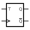
T flip-flops
A T flip-flop is a device which swaps or "toggles" state every time it is triggered if the T input is asserted, otherwise it holds the current output. This behavior is described by the characteristic equation:

and can be described either of the following tables:
|
|
When T is held high, the toggle flip-flop divides the clock frequency by two; that is, if clock frequency is 4 MHz, the output frequency obtained from the flip-flop will be 2 MHz. This 'divide-by' feature has application in various types of digital counters. A T flip-flop can also be built using a JK flip-flop (J & K pins are connected together and act as T) or D flip-flop (T input and Qprev are connected to the D input through an XOR gate).