Electronics/Basic gates
< ElectronicsBasic Gates
There are 5 basic gates used in performing logic operations in Digital Electronic namely BUFFER gate, NOT gate, AND gate, OR gate, XOR gate . Each Logic Gate has A Symbol for easy to identify , a Mathematical Expression to identify mathmatic logic operation and a Truth Table to completely describe operation of the Logic Gate
Five Basic Logic Gates
Digital gates Symbol Logic Operation Mathematic Expression BUFFER 
Y = BUFFER A Y = A NOT 
Y = NOT A Y = AND 
Y = A AND B Y = A . B OR 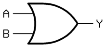
Y = A OR B Y = A + B XOR 
Y = A XOR B Y =


The Truth Table of the five basic logic gates above
A B Q = A Q = NOT A Q = A AND B Q = A OR B Q = A XOR B 0 0 0 1 0 0 0 0 1 0 1 0 1 1 1 0 1 0 0 1 1 1 1 1 0 1 1 0
Complement of Basic Logic gates
Basic Gates Combination Gates Symbol Mathematical Expression BUFFER 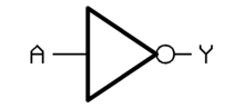
Q = is NOT NOT A
Y = ANOT Y = is NOT A NAND 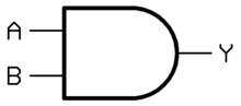

Q = NOT A AND B NOR 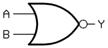
Y = NOT A OR B XNOR 
Q = NOT A XOR B
The Truth table of the combination gates above
A B Q = A Q = NOT A Q = A NAND B Q = A NOR B Q = A XNOR B 0 0 0 1 1 1 1 0 1 0 1 1 0 0 1 0 1 0 1 0 0 1 1 1 0 0 0 1
Summary
Gates Function Symbol ANSI IEC Buffer 
NOT gate (Inverter) 
AND gate 
NAND gate (NOT−AND) 
OR gate 

NOR gate (NOT−OR) 

XOR gate (Exclusive-OR) 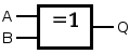
XNOR gate (NOT−exclusive−OR) 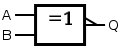
A B Q = A Q = NOT A Q = A AND B Q = A OR B Q = A XOR B Q = A NAND B Q = A NOR B Q = A XNOR B 0 0 0 1 0 0 0 1 1 1 0 1 0 1 0 1 1 1 0 0 1 0 1 0 0 1 1 1 0 0 1 1 1 0 1 1 0 0 0 1


This article is issued from Wikibooks. The text is licensed under Creative Commons - Attribution - Sharealike. Additional terms may apply for the media files.