Circuit Theory/Phasors/Examples/Example 8
< Circuit Theory < Phasors < Examples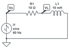
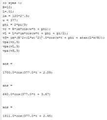
Given that the current source is defined by , find all other voltages, currents and check power.

Label Loops Junctions
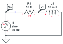
The important point is that nothing changes even though the source is oscillating. + and - still have to capture the circuit topology and work their way into the equations.
Knowns, Unknowns and Equations
- Knowns:
- Unknowns:
- Equations:


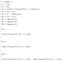
Calculus Symbolic
Evaluate the terminal relations in this order:


Calculus Numeric


Now the trouble is how to wrestle the above answer into a form where it can be compared to the other answers and our intuition built up. There are three possible ways:
- Euler
- Trig
- Phasors (which is derived from Euler).
Here is the phasor method. Notice the math is done in the phasor domain ... with imaginary numbers.


Now the numbers are in the phasor world. The next step is to add them all up.

Now put back into the time domain:

Phasors are also an alternative to the calculus above.
Because no integrals were evaluated in this calculus solution, there is no integration constant!
Phasor Symbolic
This problem could be done with Laplace transforms, but Calculus functions are less complex. It can also be done with phasors. The question is "Which mathmetical tool should be used?" Calculus above leaves the answer in a form that would require some trig to get back into the form:

The phasor solution enables us to stay close to the above solution form.
The phasor solution provides a uniform way (one tool) for doing all inductor and capacitor problems. We will use it through out the rest of the course.
time domain

phasor domain


back to time domain


Phasor Numeric
time domain

phasor domain
Rather than substituting into the time domain as last time, showing phasor (imaginary math) by substituting into the phasor domain.


back to time domain


comparison
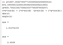
Only was calculated with both the phasor and calculus/phasor method. The number can be found in the phasor math of both the calculus method and the phasor method. But the phasor math in both sections had an intermediate calculation of R + jLw in the phasor domain. A matlab script was written for the phasor solution that merely plugged into the time domain symbolic solution. This did not allow errors to build up in matlab caused by reusing numbers .. and came up with .


The goal is to type numbers into the calculator once, or into matLab once and calculate the answers directly from the given numbers with no intermediary calculations.
Simulation
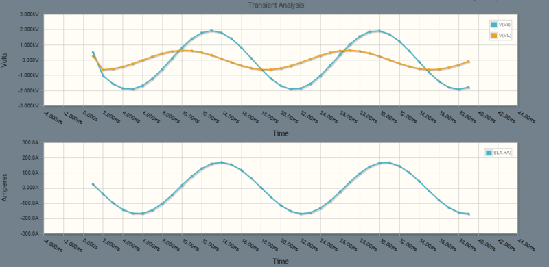 Vs,VL and I of the simulation graphed above.
period check
The period above looks to be between 16ms and 17ms, closer to 17ms. This agrees with the formula:


magnitude check
The magnitude of Vs above appears to be close to 2000 volts. This is close to 1811/1814 of the math.
The magnitude of i(t) appears to be .

The magnitude of VL appears to be above 500 volts which could be the 640 volts from the math.
Vr can not be graphed because of the choice of ground. Notice how Vr and VL share the same -. They can be measured with an oscilloscope or the above simulator. Vr can not.
transient response check
The transient response is different. The straight lines and starting above 0 seems odd. Since this is a steady state analysis, going to save digging into this until later. Otherwise, everything is the same as when driven by a voltage source.
phase check
Voltage will always lead the current through an inductor (think of the terminal relationship or ELI) by or of a period, whether a current source or voltage source is driving the circuit.


Voltage Check
Could do the phasor math again to make sure they check, but this is the math that produced the values in the first place. Here the goal is to do a quick spot check. This check is not good, but it is quick. It can detect many mistakes. At the least it builds our confidence in the answer. Need to plug into:

And make sure that they add to zero.
Pick t = 1:


The equation above is true. The actual numbers above would need more accuracy (decimal places) to get closer to zero.
Power Analysis
Power Analysis is rooted in the phasor domain!


if :, and then


and

The power is much larger ... by a factor of 100 because of the resistor, but the phase angle is still the same. This means the power factor is still the same.
| Value | Units | Description |
|---|---|---|
| volt-ampere va | apparent power what utility companies manage: peak power they design for, peak power they have to deliver | |
| unitless | power factor, ratio of real power to apparent power, ideally 1 | |
| watt W | real, average, active power ... what consumers want to pay for (watt-hours) | |
| volt-amp-reactive var | reactive power ... why not all outlets in a room are on the same circuit breaker |


Intuition
ELI ... voltage leads the current through an inductor
Derivatives cause a lag ... a delay in time ... which is a positive angle in sinusoidal.