Circuit Theory/One Port Devices
< Circuit TheoryThere are many circuits that can solve any particular task. Kirchhoff or any other analysis technique can not describe the bare minimum, most simple, alternative to an existing circuit that works.
The goal is to figure out a circuit's characteristics ... like an [w:Eigenvalue|eigenvalue] ... the minimal parameters that totally define it. The minimal characteristics or parameters serve two purposes:
- Enable design of alternative, cheaper, simpler circuits that do the same thing
- Help designers using the existing circuit predict it's impact on other circuits attached to it.
One-Port
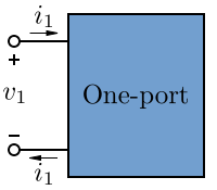
Impedance, resistance and reactance are often drawn as a rectangle instead of their normal circuit symbols. This is the beginning of dealing with the real world rather than the ideal.
A "port" hides what is inside of it like a "black box."
A resistor, capacitor, inductor or power source are one port (two wire) devices. But in the real world a resistor could also have some inductance, or capacitance, or act as a antenna channeling wireless energy into the circuit.
More generally, a one-port circuit can have any number of passive elements, independent and dependent sources and nodes. A port can be described as a circuit that has been designed, analyzed and tested. At this point, a circuit's internal details, it's design, it's theory of operation are no longer important. It becomes a building block. Complex circuits may consist of a few ports where each port itself may be complex.
When ports are named, miniaturized and mass produced, they become a new circuit device.
One port devices are usually found at the beginning and the end of a circuit. The middle of a circuit is built with two port devices, which are covered later.
A port has characteristics besides it's impedance and whether it contains a source or not. A port has parameters. The ideal parameters we have been studying are sometimes called lumped element parameters. These parameters may change depending on how the port is "driven." Ports can have different "driving points".
Example
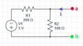
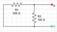
Suppose we are going to connect a DC Voltage power supply to points a and b. The goal is to characterize the insides of the box that contains a DC voltage source and a couple of resistors. Do this by:
- Plot Vab as depending upon the current (instead of the actual situation where current is dependent upon the added voltage supply) so that the slope is resistance. From the plot find the slope (resistance). What does the vertical, Vab axis intercept represent? What does the horizontal (current) axis intercept represent?
- Calculate the Vab if nothing is attached to the one port device.
- Zero the voltage source and calculate the resistance between a and b.
- Create another one port device that behaves the same with just one source and resistor. Simulate it and show that it produces the same Vab curve or line.
 Circuit that problem statement is referring to
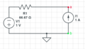
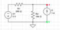 Since current is on the independent (x) axis and voltage is dependent, need a current source.
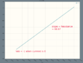 Simulation that can be found at circuitlab.com
Plot Vab
- Circuit was simulated at circuitlab resulting in the plot above that matches the formula below.
- Slope of the line is 66.66667 ohms and the intercept is -1 volt.
- The equation of the line can be formed by node analysis at a:
- Solving for Vab
- Can see in the simulation that the intercept when i = 0 is -1 and slope is 200/3.


Calculate Vab with nothing attached
Nothing attached means the current is zero, so from the equation Vab=-1 ... which is the Vab vertical axis intercept.
Zero voltage source, calculate resistance between a and b
After shorting the voltage source, have 200 and 100 ohm resistors in parallel so:

which is the slope of the equation.
Create simpler one port device
 simple circuit the performs exactly the same way as the more complicated one
- simulation at circuitlab.com is same as the 2 resistor circuit with -3 volt source