Circuit Idea/Bistable Mode of Current Inversion NIC
< Circuit Idea
<<< contents - bistable VNIC - linear INIC - linear VNIC - negative impedance - page stage >>>
Investigating the Bistable Mode of Negative Impedance Converters with Current Inversion
Circuit idea: Making the positive feedback dominate over the negative one.
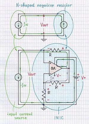
INIC operating in bistable mode is a current-driven N-shaped true negative resistor.
Introduction
How to investigate the bistable mode of current inversion NIC
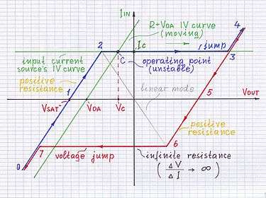 Fig. 1a: A hysteresis IV curve of current-driven INIC.
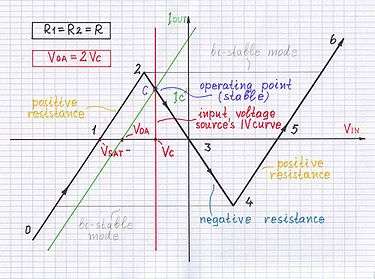 Fig. 1b: An N-shaped IV curve of voltage-driven INIC.
Investigating the circuit at ideal driving conditions
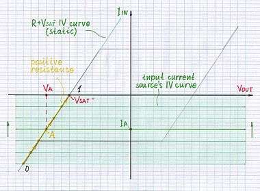 Fig. 2a: Scanning the left bottom part (0 - 1) of the curve.
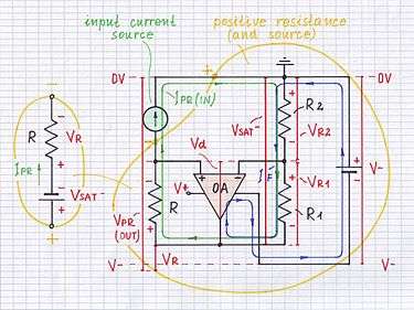 Fig. 2b: Sinking a current from INIC.
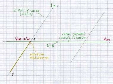 Fig. 3a: Investigating the point 1 of the curve.
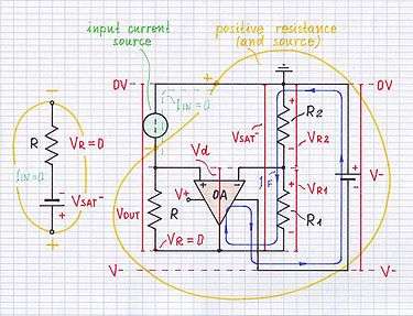 Fig. 3b: Sinking no current from INIC.
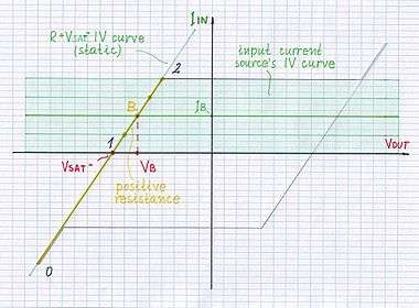 Fig. 4a: Scanning the left top part (1 - 2) of the curve.
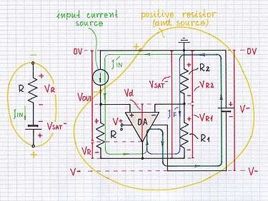 Fig. 4b: Injecting a current to INIC.
Voltage jump upward:
...start...
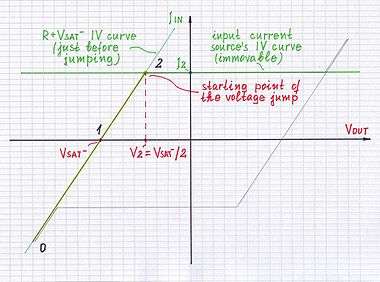 Fig. 5-1a: Investigating the starting point of the voltage jump.
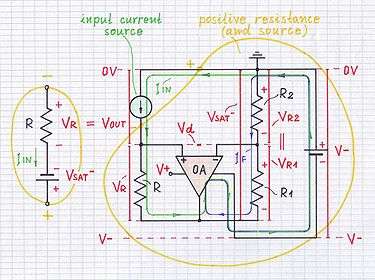 Fig. 5-1b: Making the op-amp "jump" to the positive rail.
...middle...
 Fig. 5-2a: Scanning the top jumping path (2 - 3).
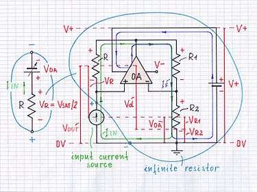 Fig. 5-2b: The op-amp "jumps" to the positive rail.
...final
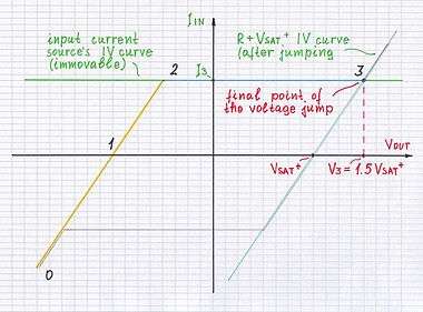 Fig. 5-3a: Investigating the final point of the voltage jump upward.
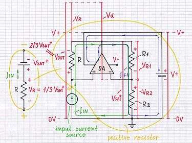 Fig. 5-3b: The op-amp "calms down" at the positive rail.
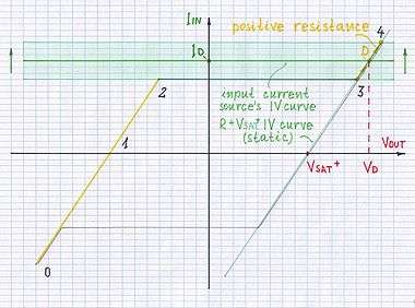 Fig. 6a: Scanning the right top part (3 - 4) of the curve.
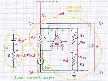 Fig. 6b: Injecting a big current to INIC.
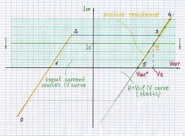 Fig. 7a: Scanning the right top part (4 - 5) of the curve.
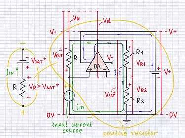 Fig. 7b: Injecting a current to INIC.
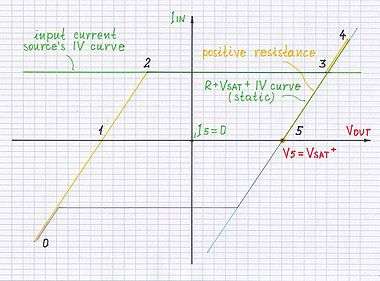 Fig. 8a: Investigating the point 5 of the curve.
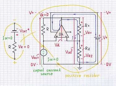 Fig. 8b: Injecting no current to VNIC.
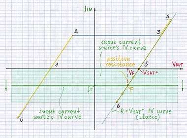 Fig. 9a: Scanning the right bottom part (5 - 6) of the curve.
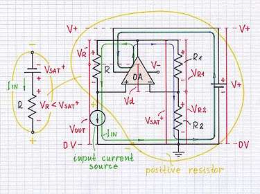 Fig. 9b: Sinking a current from INIC.
Voltage jump downward:
...start...
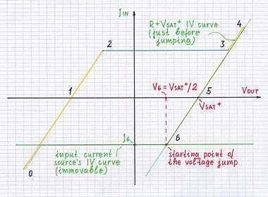 Fig. 10-1a: Investigating the starting point of the voltage jump.
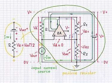 Fig. 10-1b: Making the op-amp "jump" to the negative rail.
...middle...
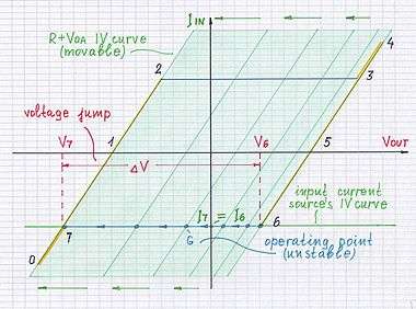 Fig. 10-2a: Scanning the bottom jumping path (6 - 7).
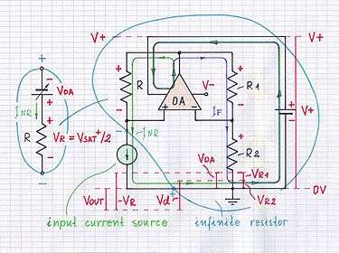 Fig. 10-2b: The op-amp "jumps" to the negative rail.
...final
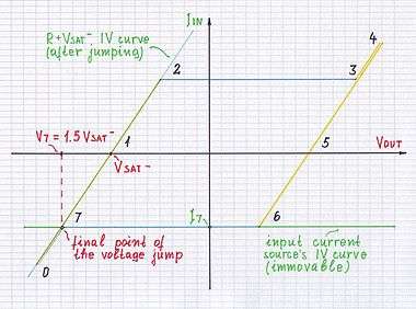 Fig. 10-3a: Investigating the final point of the voltage jump downward.
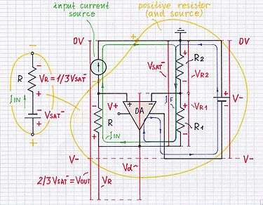 Fig. 10-3b: The op-amp "calms down" at the negative rail.
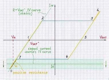 Fig. 11a: Scanning the left bottom part (7 - 0) of the curve.
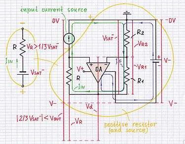 Fig. 11b: Siniking a big current from INIC.
What is the relation with the non-inverting comparator with hysteresis?
References
See also
Revealing the mystery of negative impedance
Investigating the linear mode of negative impedance converters with current inversion
Negative impedance converter from Wikipedia considers NIC with current inversion (INIC).
External links
<<< top - contents - bistable VNIC - linear INIC - linear VNIC - negative impedance - page stage >>>