Cg Programming/Unity/Hermite Curves
< Cg Programming < Unity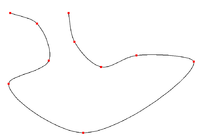
This tutorial discusses Hermite curves (more exactly: cubic Hermite curves) and Catmull-Rom splines in Unity. The latter are a special kind of cubic Hermite splines. No shader programming is required since all the code is implemented in JavaScript.
Some splines (for example the quadratic Bézier spline discussed in Section “Bézier Curves”) don't go through all control points, i.e. they don't interpolate between them. Hermite splines, on the other hand, can be defined such that they go through all control points. This is a useful feature in many applications, e.g. in animation where it is often important to set specific values for particular key frames and let tools smoothly interpolate further values for inbetweens.
Hermite Curves
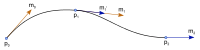
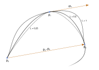
A single cubic Hermite curve for from 0 to 1 is defined by a start point with tangent and an end point with tangent :


The curve starts (for ) at in direction of and then changes course to direction and reaches for . As the figure illustrates, two Hermite curves can be smoothly attached to each other by choosing the same tangent vector for the corresponding end points.


Curve Script
To implement such a curve in Unity, we can use the Unity component LineRenderer. Apart from setting some parameters, one should set the number of sample points on the curve with the function SetVertexCount. Then the sample points have to be computed and set with the function SetPosition. This is can be implemented this way:
   var t : float;
   var position : Vector3;
   for(var i : int = 0; i < numberOfPoints; i++)
   {
      t = i / (numberOfPoints - 1.0);
      position = (2.0*t*t*t - 3.0*t*t + 1.0) * p0
         + (t*t*t - 2.0*t*t + t) * m0
         + (-2.0*t*t*t + 3.0*t*t) * p1
         + (t*t*t - t*t) * m1;
      lineRenderer.SetPosition(i, position);
   }
Here we use an index i from 0 to numberOfPoints-1 to count the sample points. From this index i a parameter t from 0 to 1 is computed. The next line computes , which is then set with the function SetPosition.
The rest of the code just sets up the LineRenderer component and defines public variables that can be used to define the control points and some rendering features of the curve.
@script ExecuteInEditMode()
#pragma strict

public var start : GameObject;
public var startTangentPoint : GameObject;
public var end : GameObject;
public var endTangentPoint : GameObject;

public var color : Color = Color.white;
public var width : float = 0.2;
public var numberOfPoints : int = 20;

function Start()
{
   // initialize line renderer component
   var lineRenderer : LineRenderer =
      GetComponent(LineRenderer);
   if (null == lineRenderer)
   {
      gameObject.AddComponent(LineRenderer);
   }
   lineRenderer = GetComponent(LineRenderer);
   lineRenderer.useWorldSpace = true;
   lineRenderer.material = new Material(
      Shader.Find("Particles/Additive"));
}

function Update()
{
   // check parameters and components
   var lineRenderer : LineRenderer =
      GetComponent(LineRenderer);
   if (null == lineRenderer
      || null == start || null == startTangentPoint
      || null == end || null == endTangentPoint)
   {
      return; // no points specified
   }

   // update line renderer
   lineRenderer.SetColors(color, color);
   lineRenderer.SetWidth(width, width);
   if (numberOfPoints > 0)
   {
      lineRenderer.SetVertexCount(numberOfPoints);
   }

   // set points of Hermite curve
   var p0 : Vector3 = start.transform.position;
   var p1 : Vector3 = end.transform.position;
   var m0 : Vector3 = startTangentPoint.transform.position
      - start.transform.position;
   var m1 : Vector3 = endTangentPoint.transform.position
      - end.transform.position;
   var t : float;
   var position : Vector3;
   for(var i : int = 0; i < numberOfPoints; i++)
   {
      t = i / (numberOfPoints - 1.0);
      position = (2.0*t*t*t - 3.0*t*t + 1.0) * p0
         + (t*t*t - 2.0*t*t + t) * m0
         + (-2.0*t*t*t + 3.0*t*t) * p1
         + (t*t*t - t*t) * m1;
      lineRenderer.SetPosition(i, position);
   }
}
To use this script create a Javascript in the Project Window, double-click it, copy & paste the code above, save it, create a new empty game object (in the main menu: GameObject > Create Empty) and attach the script (drag the script from the Project Window over the empty game object in the Hierarchy Window).
Then create four more empty game objects (or any other game objects) with different(!) positions that will serve as control points. Select the game object with the script and drag the other game objects into the slots Start, StartTangentPoint (for the end point of a tangent starting in the start point), End, and EndTangentPoint in the Inspector. This should render a Hermite curve from the game object specified as “Start” to the game object specified as “End”.
Catmull-Rom Splines
A cubic Hermite spline consists of a continuous, smooth sequence of cubic Hermite curves. In order to guarantee smoothness, the tangent at the end point of one Hermite curve is the same as the tangent of the start point of the next Hermite curve. In some cases, users provide these tangents (one for each control point), in other cases, however, appropriate tangents have to be computed.
One specific way of computing a tangent vector for the k-th control point is this:


and for the first point and for the last point. The resulting cubic Hermite spline is called Catmull-Rom spline.


Spline Script
The following script implements this idea. For the j-th segment, it computes as the j-th control point , is set to , is set to (unless it is the tangent of the first control point, in which case it is set to ) and is set to (unless it is the tangent of the last control point, then it is set to ).


      p0 = controlPoints[j].transform.position;
      p1 = controlPoints[j + 1].transform.position;
      if (j > 0)
      {
         m0 = 0.5 * (controlPoints[j + 1].transform.position
         - controlPoints[j - 1].transform.position);
      }
      else
      {
         m0 = controlPoints[j + 1].transform.position
         - controlPoints[j].transform.position;
      }
      if (j < controlPoints.length - 2)
      {
         m1 = 0.5 * (controlPoints[j + 2].transform.position
         - controlPoints[j].transform.position);
      }
      else
      {
         m1 = controlPoints[j + 1].transform.position
         - controlPoints[j].transform.position;
      }
Each individual segment is then just computed as a cubic Hermite curve. The only adjustment is that all but the last segment should not reach . If they did, the first sample position of the next segment would be at the same position which would be visible in the rendering. The complete script is:
@script ExecuteInEditMode()
#pragma strict

public var controlPoints : GameObject[] = new GameObject[3];
public var color : Color = Color.white;
public var width : float = 0.2;
public var numberOfPoints : int = 20;

function Start()
{
   // initialize line renderer component
   var lineRenderer : LineRenderer =
      GetComponent(LineRenderer);
   if (null == lineRenderer)
   {
      gameObject.AddComponent(LineRenderer);
   }
   lineRenderer = GetComponent(LineRenderer);
   lineRenderer.useWorldSpace = true;
   lineRenderer.material = new Material(
      Shader.Find("Particles/Additive"));
}

function Update()
{
   // check parameters and components
   var lineRenderer : LineRenderer =
      GetComponent(LineRenderer);
   if (null == lineRenderer || controlPoints == null
      || controlPoints.length < 2)
   {
      return; // not enough points specified
   }

   // update line renderer
   lineRenderer.SetColors(color, color);
   lineRenderer.SetWidth(width, width);
   if (numberOfPoints < 2)
   {
      numberOfPoints = 2;
   }
   lineRenderer.SetVertexCount(numberOfPoints *
      (controlPoints.length - 1));

   // loop over segments of spline
   var p0 : Vector3;
   var p1 : Vector3;
   var m0 : Vector3;
   var m1 : Vector3;
   for (var j : int = 0; j < controlPoints.length - 1; j++)
   {
      // check control points
      if (controlPoints[j] == null ||
         controlPoints[j + 1] == null ||
         (j > 0 && controlPoints[j - 1] == null) ||
         (j < controlPoints.length - 2 &&
         controlPoints[j + 2] == null))
      {
         return;
      }
      // determine control points of segment
      p0 = controlPoints[j].transform.position;
      p1 = controlPoints[j + 1].transform.position;
      if (j > 0)
      {
         m0 = 0.5 * (controlPoints[j + 1].transform.position
         - controlPoints[j - 1].transform.position);
      }
      else
      {
         m0 = controlPoints[j + 1].transform.position
         - controlPoints[j].transform.position;
      }
      if (j < controlPoints.length - 2)
      {
         m1 = 0.5 * (controlPoints[j + 2].transform.position
         - controlPoints[j].transform.position);
      }
      else
      {
         m1 = controlPoints[j + 1].transform.position
         - controlPoints[j].transform.position;
      }

      // set points of Hermite curve
      var position : Vector3;
      var t : float;
      var pointStep : float = 1.0 / numberOfPoints;
      if (j == controlPoints.length - 2)
      {
         pointStep = 1.0 / (numberOfPoints - 1.0);
         // last point of last segment should reach p1
      }
      for(var i : int = 0; i < numberOfPoints; i++)
      {
         t = i * pointStep;
         position = (2.0*t*t*t - 3.0*t*t + 1.0) * p0
            + (t*t*t - 2.0*t*t + t) * m0
            + (-2.0*t*t*t + 3.0*t*t) * p1
            + (t*t*t - t*t) * m1;
         lineRenderer.SetPosition(i + j * numberOfPoints,
            position);
      }
   }
}
The script works in the same way as the script for Hermite curves except that the user can specify an arbitrary number of control points and doesn't have to specify tangent points.
Summary
In this tutorial, we have looked at:
- the definition of cubic Hermite curves and Catmull-Rom splines
- implementations of cubic Hermite curves and Catmull-Rom splines with Unity's LineRenderer component.
Further Reading
If you want to know more
- about Hermite splines, the Wikipedia article on “cubic Hermite spline” provides a good starting point.
- about Unity's LineRenderer, you should read Unity's documentation of the class LineRenderer.